Tele-Centric Photography Explorations - Isometric View in Real Life
Table of Contents
When working on PCB designs, I fount it quite often necessary to create footprints for the parts I was going to use. Accompanying the footprints were the 3D models, sometimes just called CAD models. Big name suppliers usually provide them in STEP, BXL, or other similar file formats, but lesser-known brands will likely not give such resources. When this was the case, my second best choice would be to measure the drawings on the component datasheets. However, this method was not always reliable, as the figures might be out of scale. Then, the only option left was to take pictures of the actual component, and measuring the features by the pixel. This was a very labor-intensive process. For example, each of the OLED display models below took me several hours to create. Despite this, I still tried to have as much 3D models on my PCB as possible since the look they bring was very satisfying.
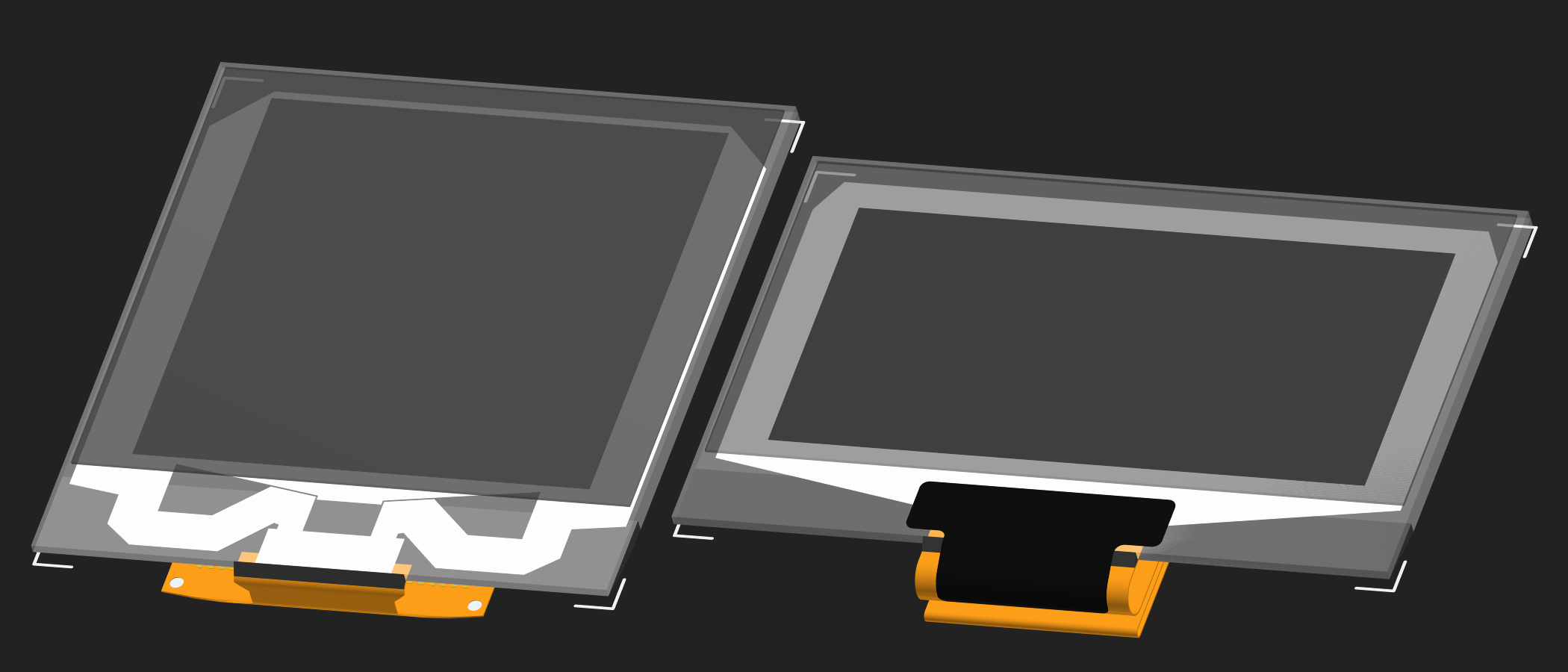
This is where tele-centric lenses come in. I won’t go into the details of how they work optically, but in short, they’re a type of lens that eliminates perspective, and gives you an image where the size of an object is independent on how far it is from the camera. Checkout the Wiki page if you’re interested, it is essentially the real-life counterpart of the isometric view functionalities in CAD software. When I learned the existence of it, I knew immediately that I needed one. When you want accurate measurements from pictures, removing perspective is pretty much mandatory.
Edmund 56-675 Lens
After some research, I purchased a second-hand Edmund 56-675. My decision was mostly driven by the FOV of the lens versus cost. Since the view is parallel, the lens cannot capture objects larger in diameter than itself. In practice, the maximum size of objects will be even more limited. According to its spec sheet (archive ), the horizontal FOV of this particular model is only 40mm for 1/2" sensors, and 30mm for 1/3" sensors. This is tiny compared to regular camera lenses that can capture mountains or buildings, but it can cover most PCB components. A larger lens will cost more and weigh more, a smaller one will probably be less useful for things like relays, display panels, or other unusual and large parts.
To be fair, I could use the fact that the view is isometric, and make a motorized X-Y mechanism to tile multiple images captured with a smaller FOV lens, but this was a bit too complicated and bulky for my purpose, so I’m gonna set this option aside.
The Edmund 56-675 was not the cheapest, but seemed to be a good compromise. I spent around 200 USD total on it in Jan 2025, right when the import tariffs went into effect, ouch. The lens uses C-mount, and my task was to figure out what camera should I mount it onto to make an easy-to-use solution. This seemed a little backwards, but the lens really was more important than the camera in this application. I’ve tried 4 cameras as of this writing, an RF4 microscope C-mount camera, a Canon DSLR with C-mount to EF-S adapter, a Raspberry Pi High Quality Camera, and a Sony mirrorless with C-Mount to E-Mount adapter.
RF4 Microscope C-Mount Camera
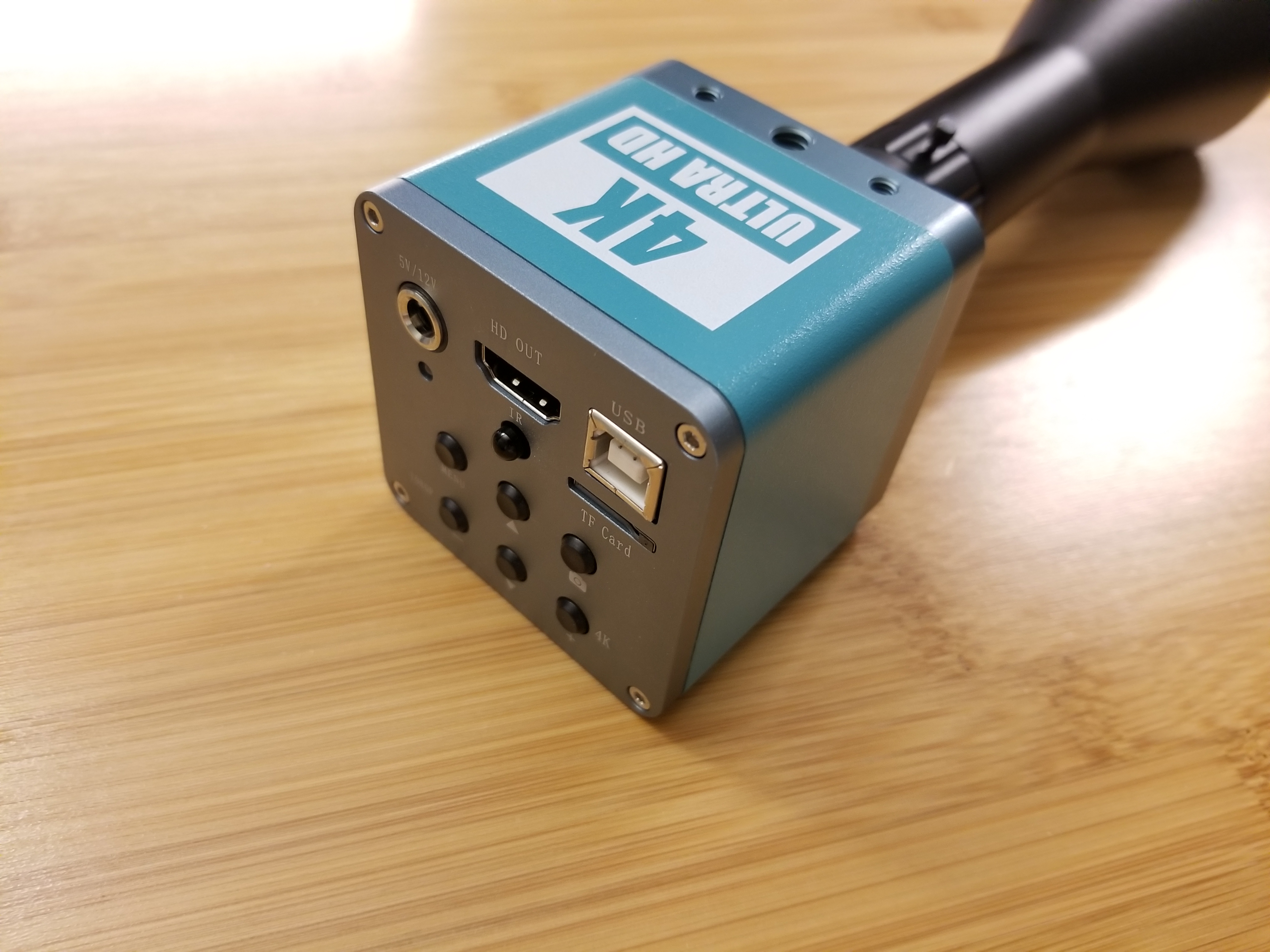
Lens mounted to RF4 microscope C-mount camera
This was the first camera I tired with the lens. It came with my soldering microscope, takes 5V or 12V DC from a barrel jack, and outputs the live preview image through HDMI to an external monitor. The pictures were stored in a micro SD card. While you can get it to work as a USB webcam, that limit its resolution and you’ll still need the power cable. Let’s take some pictures with it…
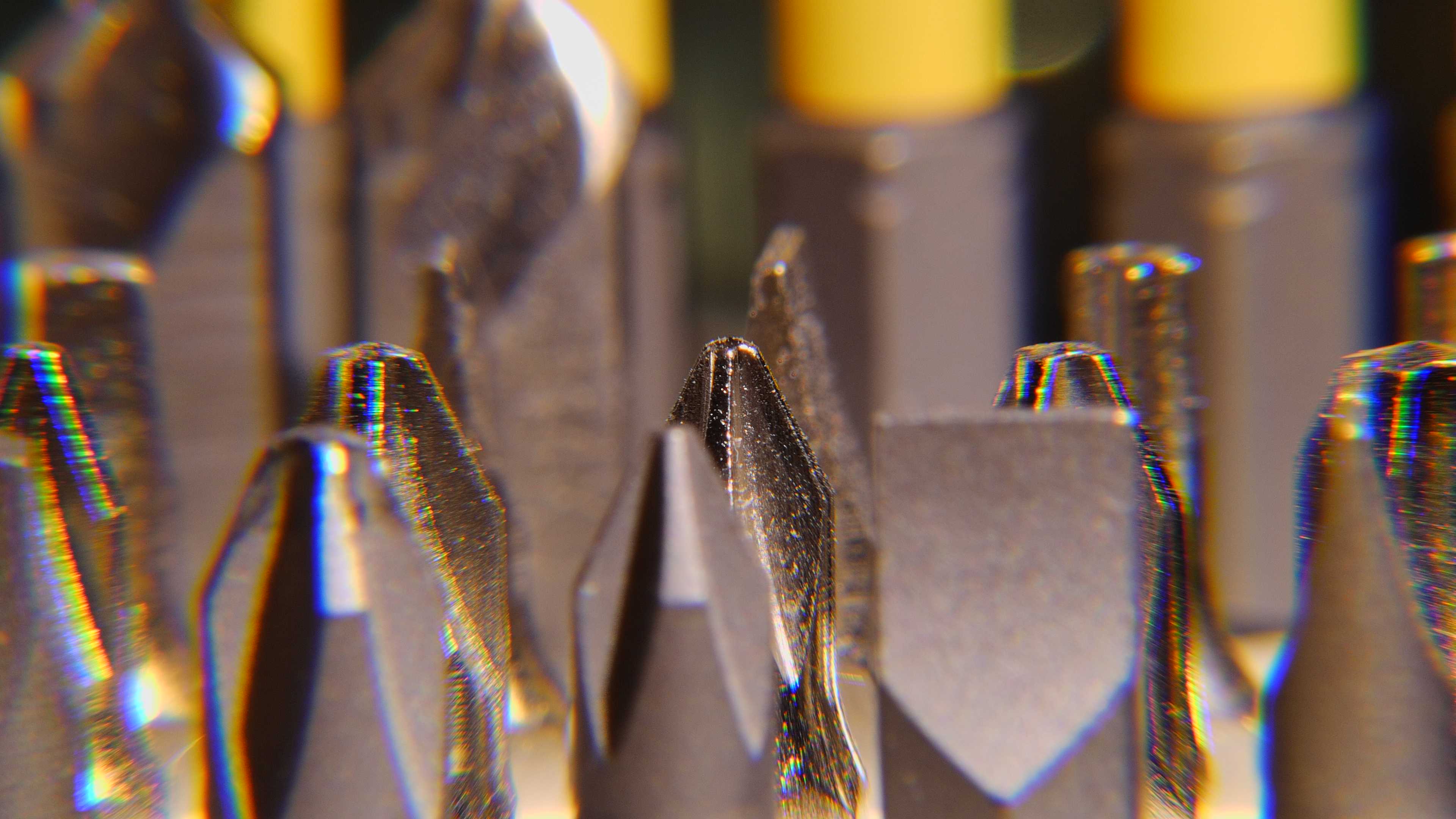
Screw driver bits, notice the ones further away didn't appear to be closer together.
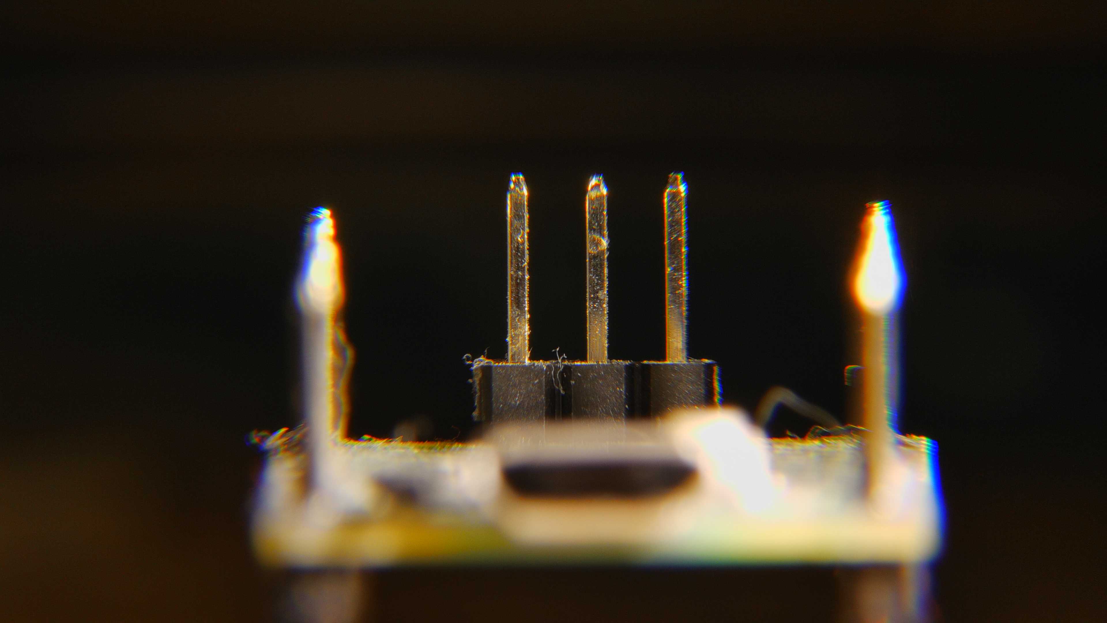
Raspberry Pi Pico RP2040 dev board, header pins perfectly lined up when viewed upfront.
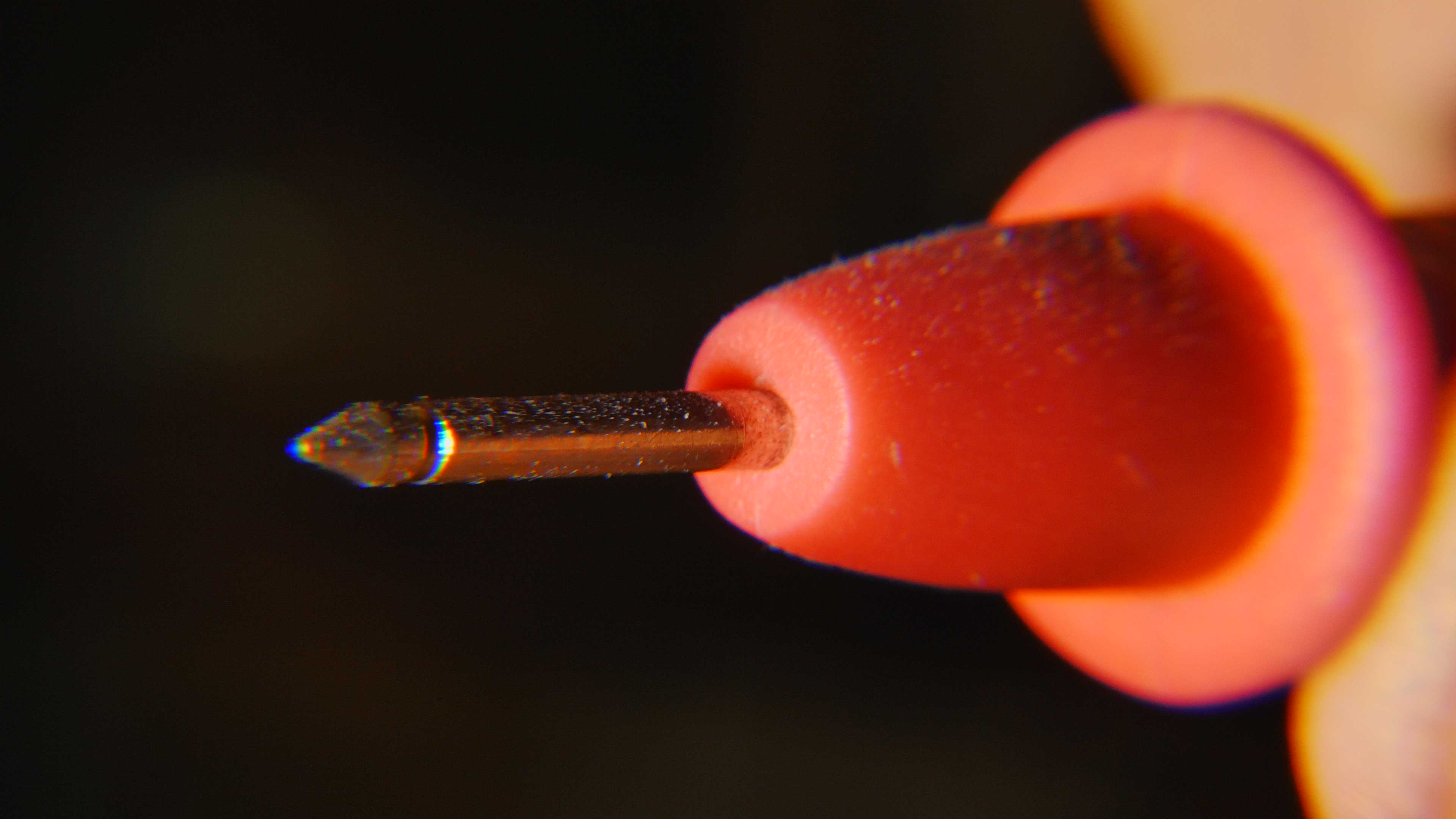
Multimeter lead tip
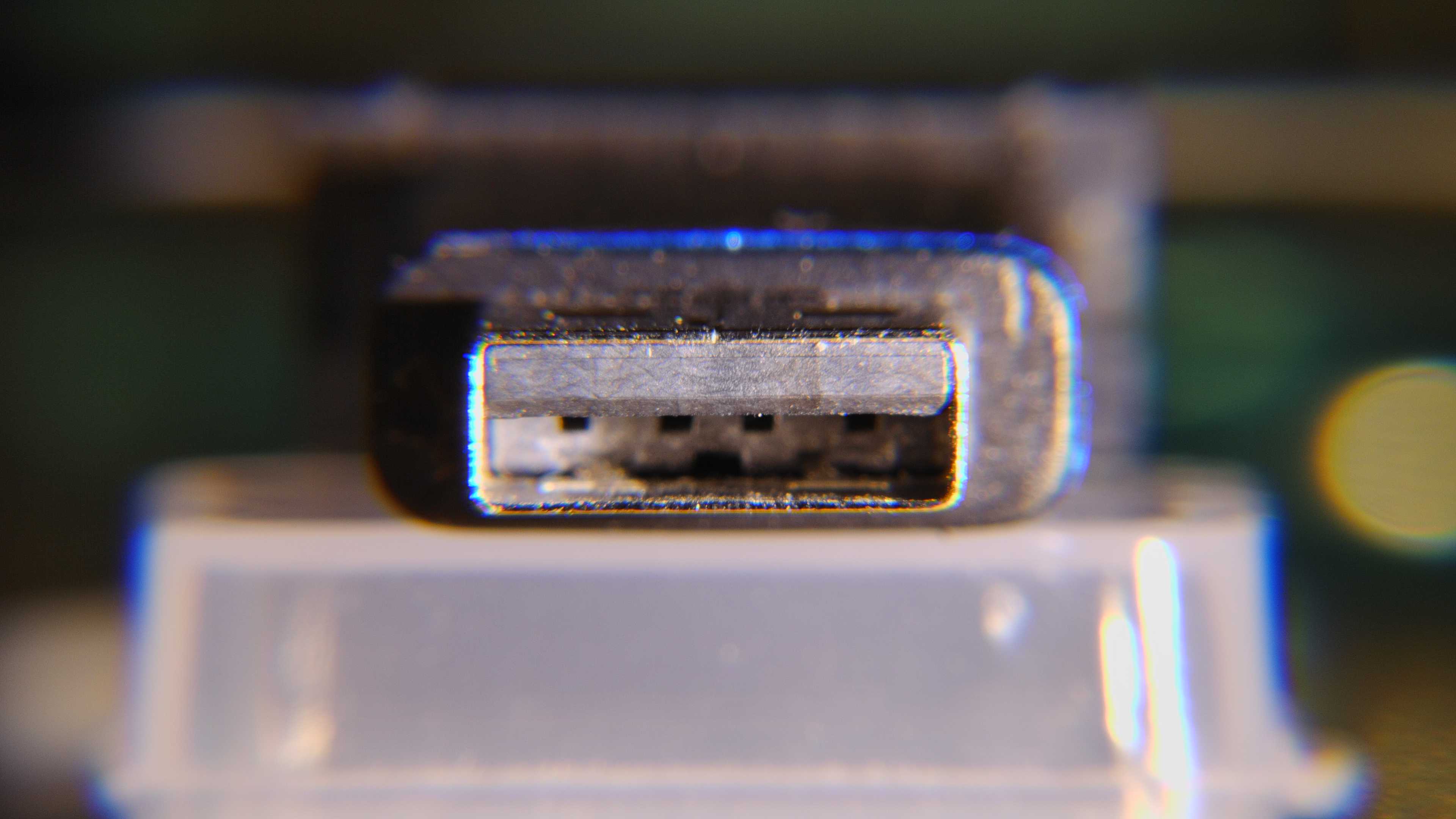
USB A connector
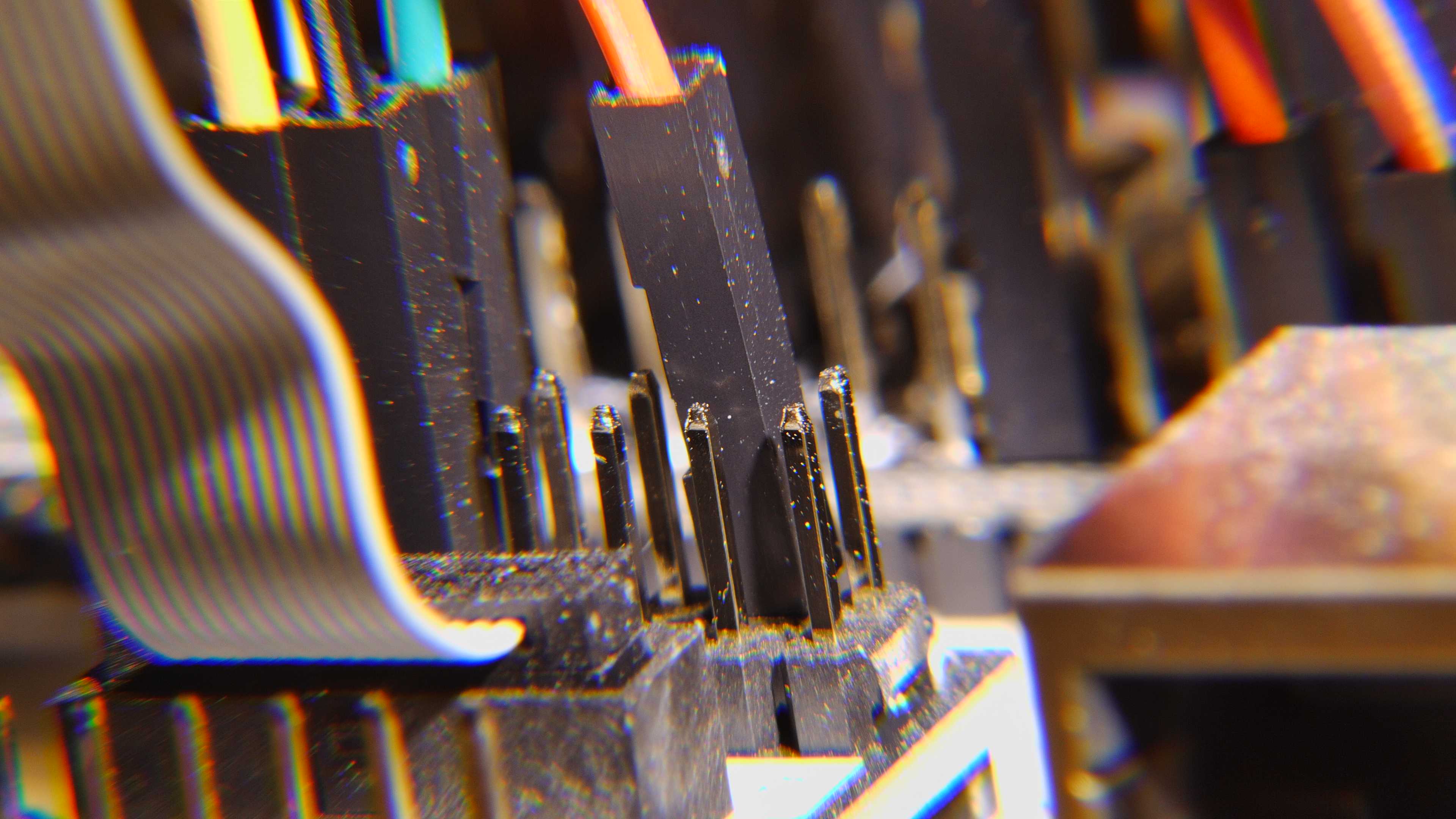
Part of a breadboard setup
Well it was isometric alright. No perspective at all, but the image quality left a lot to be desired. The focus seemed a bit shallow, probably fixable by adjusting the aperture, but what was going on with the chromatic aberration near the edges?!
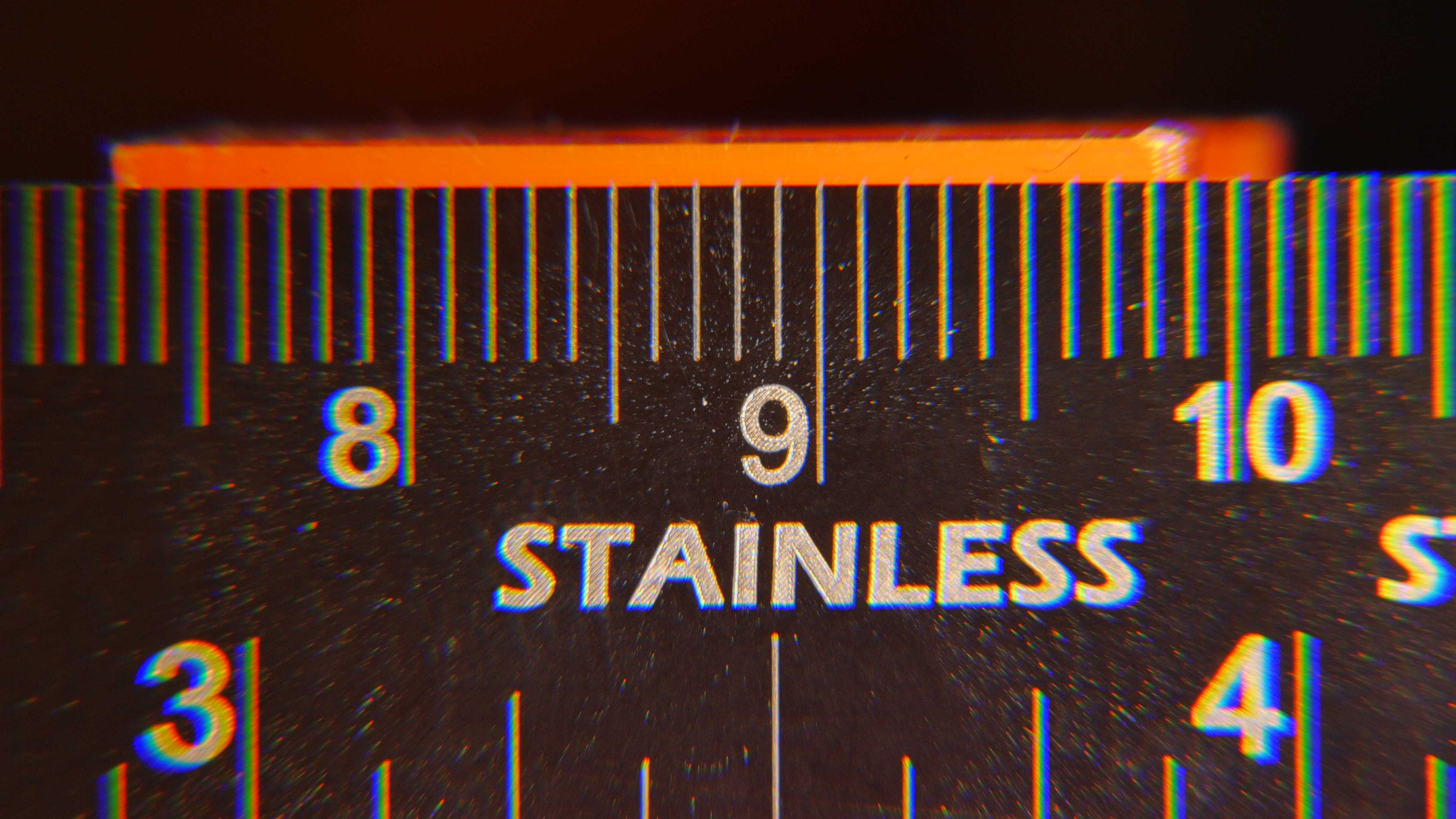
Test Image of a ruler
Hmm, this is no good. Although it’s possible to correct the chromatic aberration through software, any measurements will likely be off. I was not sure why this happened, but had 2 theories.
Since the camera was sold with a microscope, the manufacturer probably didn’t strictly adhere to the C-mount standard for Flange Focal Distance of 17.526 mm, and only used the thread size instead. As a result, the camera worked fine with the microscope it was designed to work with, but not other C-mount lenses. Those will mechanically fit, but not focus correctly, as the sensor was not at the right distance away.
The camera was actually CS-mount, which had the same thread specification as C-mount, but 12.526 mm flange focal distance. The description from the camera manufacturer was not very clear on this part.
Additionally, operating this camera was not as “clean and simple” as I expected. It needed both a power input and a display output, so I had to constantly fight with tangling cables. It also had little image adjustment options, with settings you’d expect from a webcam rather than a DSLR. I mean, sure, it was good enough for what it was designed for, but there must be a better solution.
Canon DSLR with C-Mount to EF-S Adapter
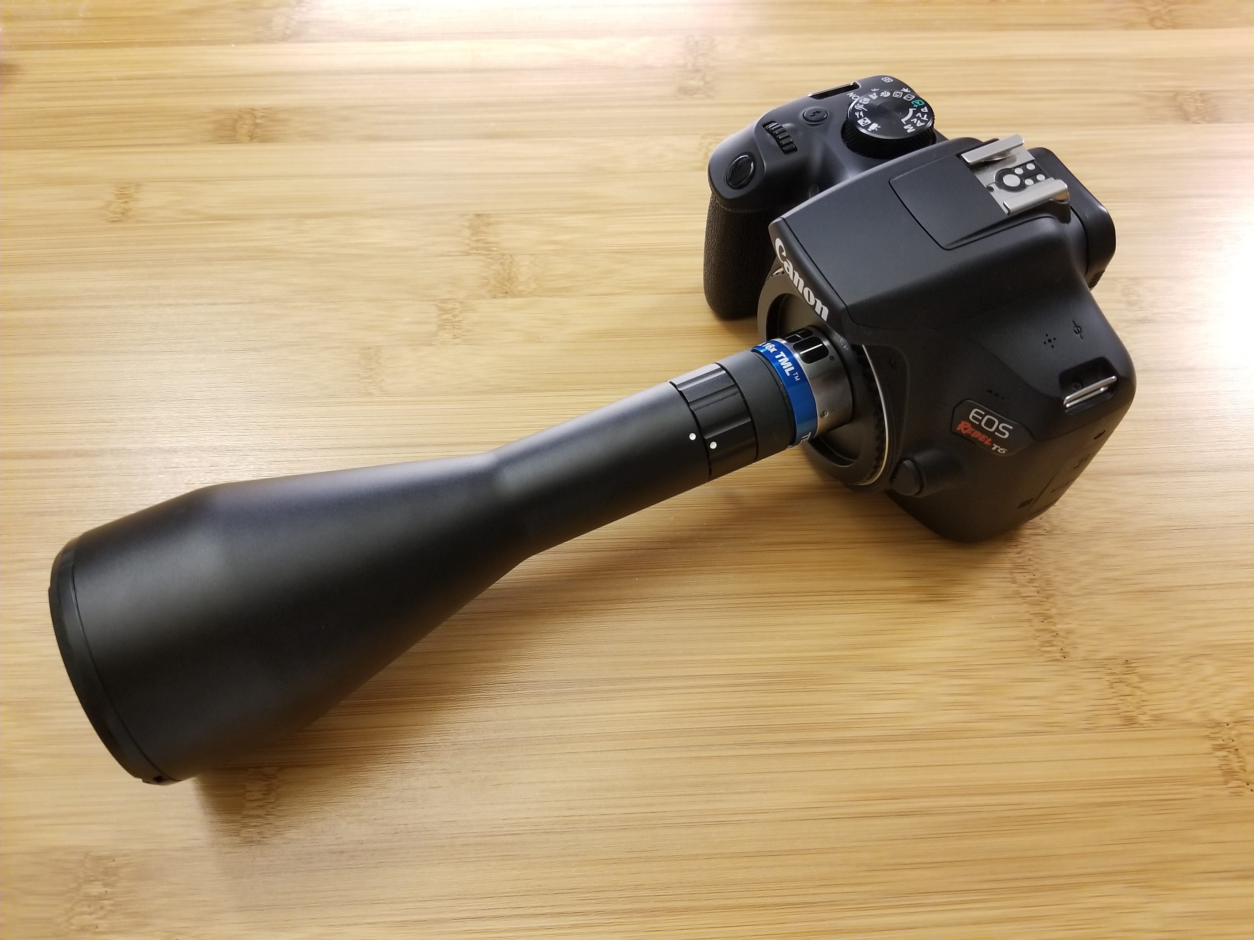
Lens mounted to Canon DSLR with C-mount to EF-S adapter
This was an interesting combination that I knew will never work. The concept of flange focal distance came back into play, and for the Canon Rebel T6 I had, the distance was 44 mm (EF-S mount). This was way longer than the 17.526 mm for C-mount. Which meant a C-mount lens would need to physically move into the camera’s lens flange by 26.474 mm just to get to the right location (closer to the sensor). The space right in front of the sensor was, of course, taken by the mirror mechanisms, so this kind of adaptation was impossible. I ordered the adapter just to see what would happen, the result was quite funny.
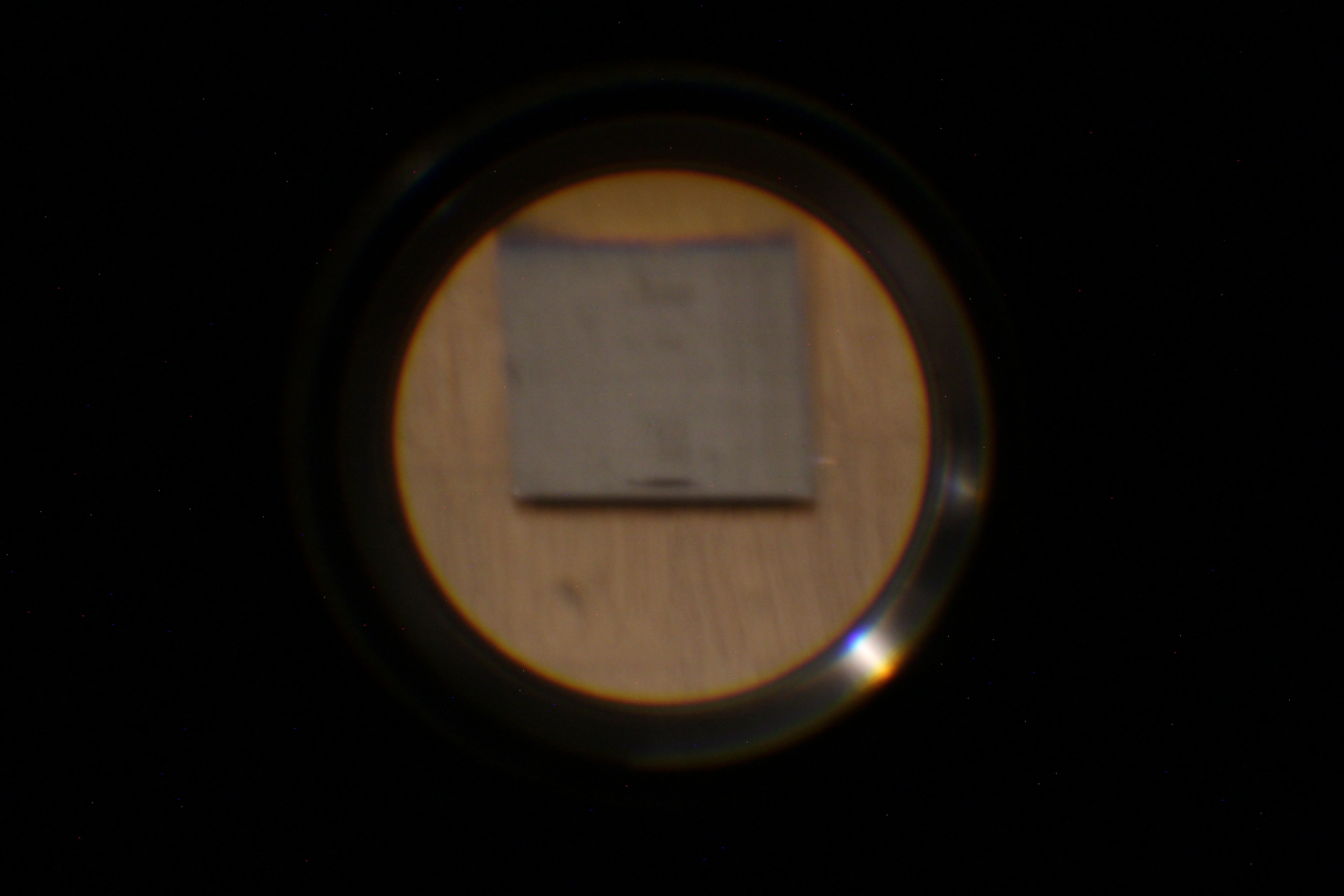
Test image with the lens adapter
What we see here was a steel ruler, seen from one end. I was completely unable to get it into focus, but surprisingly you can still see the overall shape being preserved. The ruler fore-shortened into almost a square. If the picture was taken with a regular camera, it would look something like this.
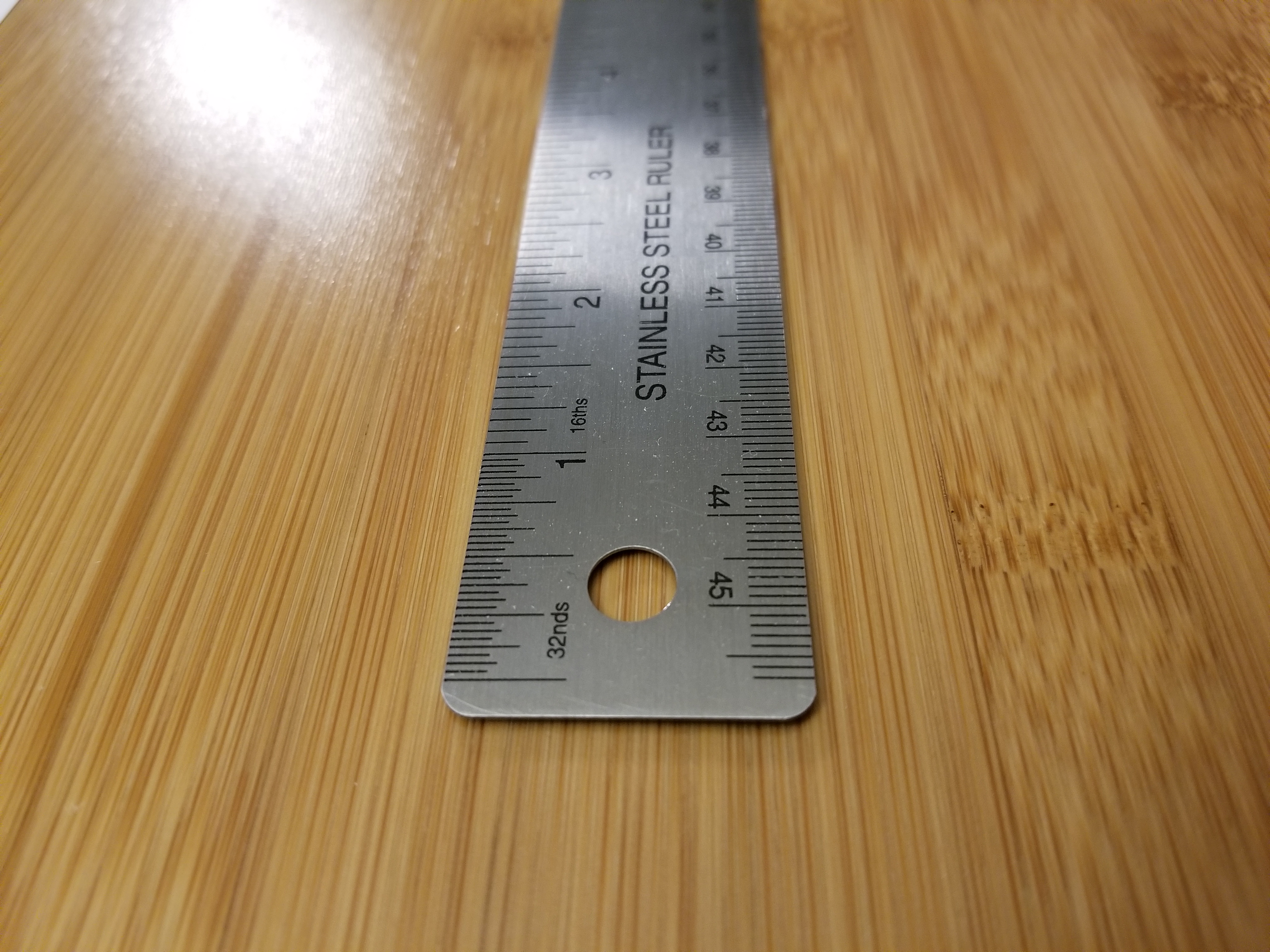
What this setup would normally look like
Another problem with this set up was that C-mount cameras typically had smaller sensors than a DSLR or mirrorless, so C-mount lenses were designed to project the image to a smaller area. This will waste most of the resolution of a full-frame camera, I’ll cover this issue in greater detail later .
Raspberry Pi High Quality Camera
Since I was basically building my own camera at this point, why not include a more bare-bones solution? The Raspberry Pi High Quality Camera seemed like an interesting choice. It was designed to be C-mount, so it had a small sensor with high resolution (1/2.3", 12.3 MP, source ). One limitation was that it must be connected to a Raspberry Pi to work, but luckily I had a spare one. Taking pictures with a pile of loose boards would still suck, so I designed and printed some basic brackets to attach everything to the lens. Some space for a USB battery bank was also reserved, so the contraption can work without being tethered by a power cable.
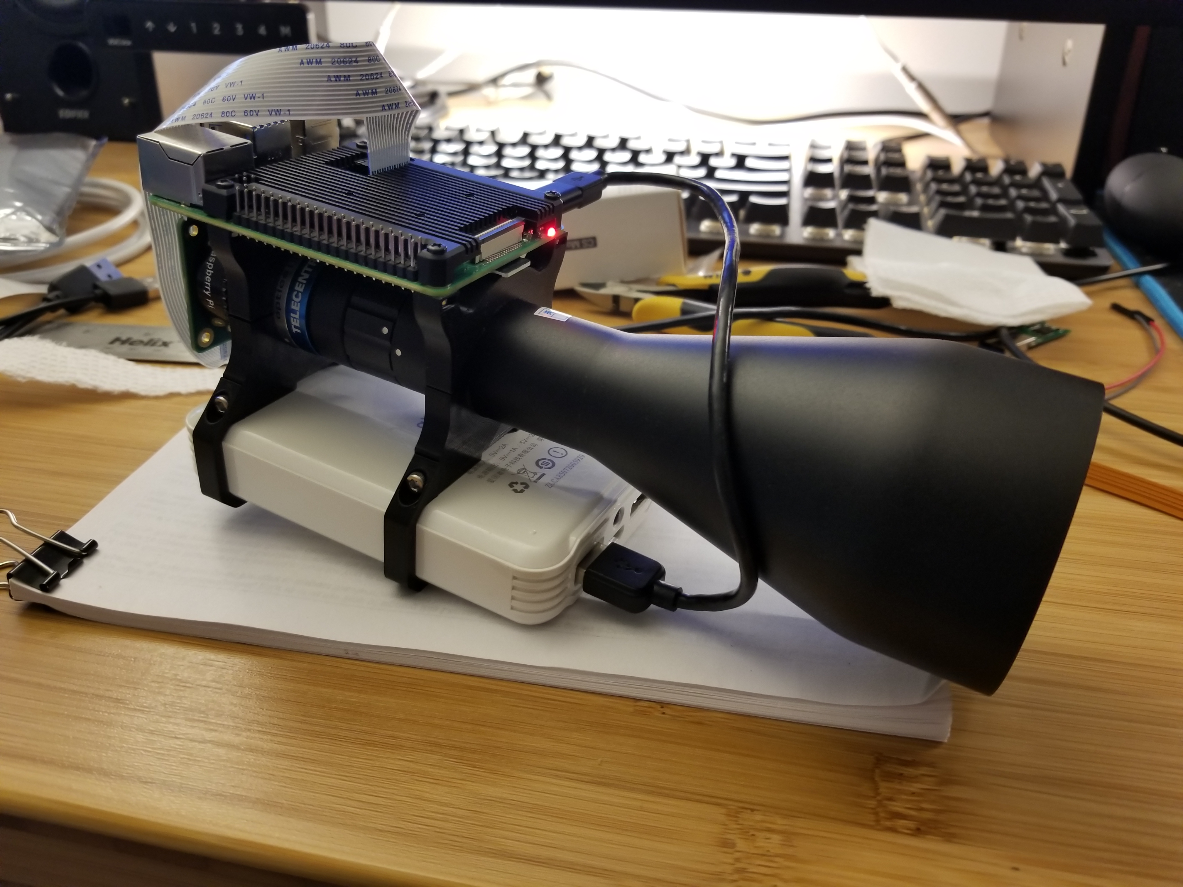
Raspberry Pi High Quality Camera setup
Taking pictures with this setup was quite an adventure. I connected to the Raspberry Pi through both a VNC and an SSH session. The VNC connection was for getting the preview image, while the SSH was for file transfer and miscellaneous terminal operations.
To get the preview window, I used the following Python script:
#!/usr/bin/python3

import time
from picamera2 import Picamera2, Preview
from libcamera import Transform

picam2 = Picamera2()
picam2.start_preview(Preview.QTGL)

preview_config = picam2.create_preview_configuration(transform=Transform(hflip=1, vflip=1))
picam2.configure(preview_config)

picam2.start()
time.sleep(1200)
And then to take a picture, I used this terminal command:
rpicam-still -o <Path-to-file> --shutter 300000 --gain 1 --awbgains 0,0 --immediate --vflip --hflip
I’m sure there are better workflows for this, but let’s see if the pictures are good.
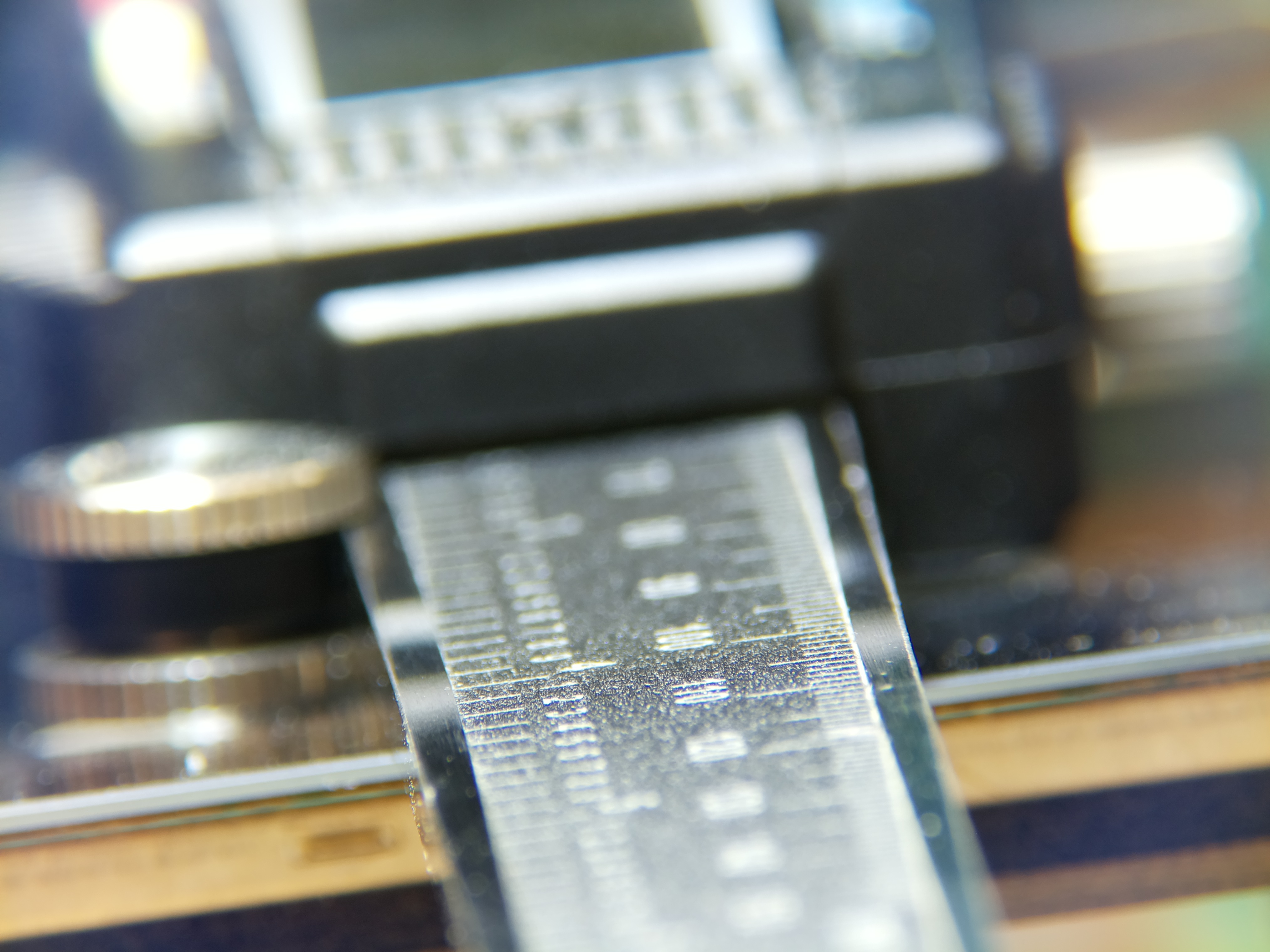
A pair of calipers, again, very isometric
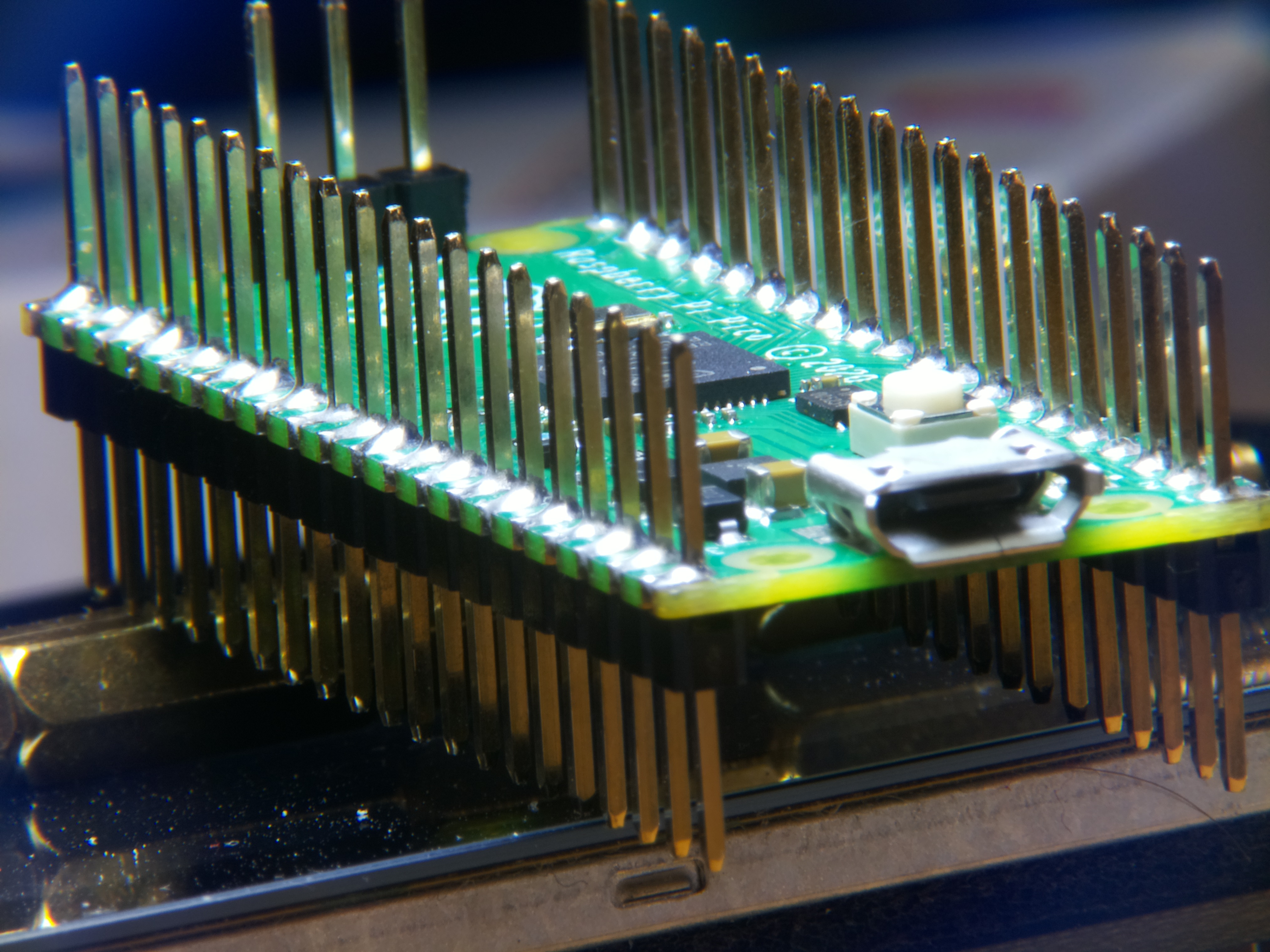
Raspberry Pi Pico RP2040 dev board
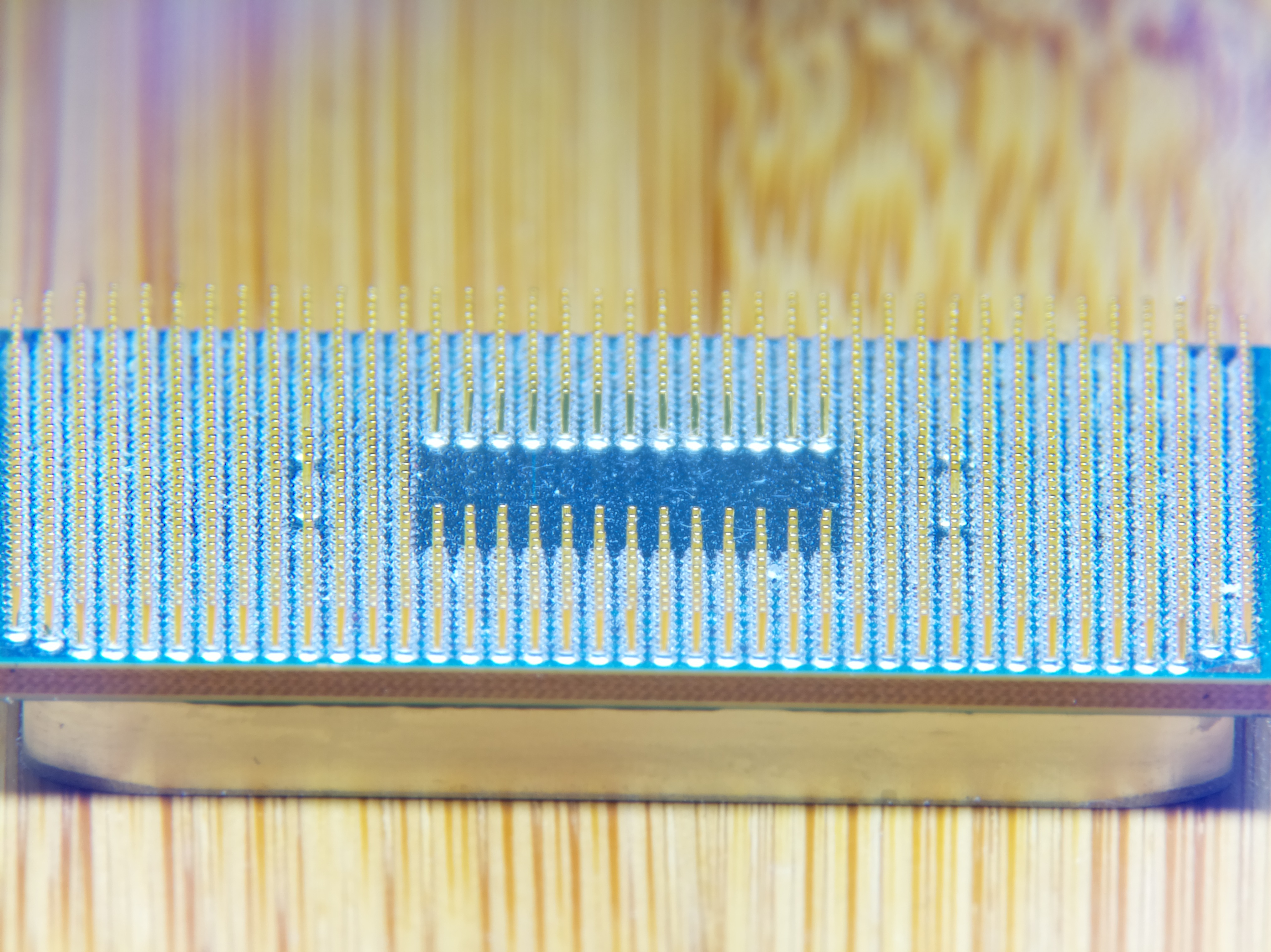
A Ryzen CPU
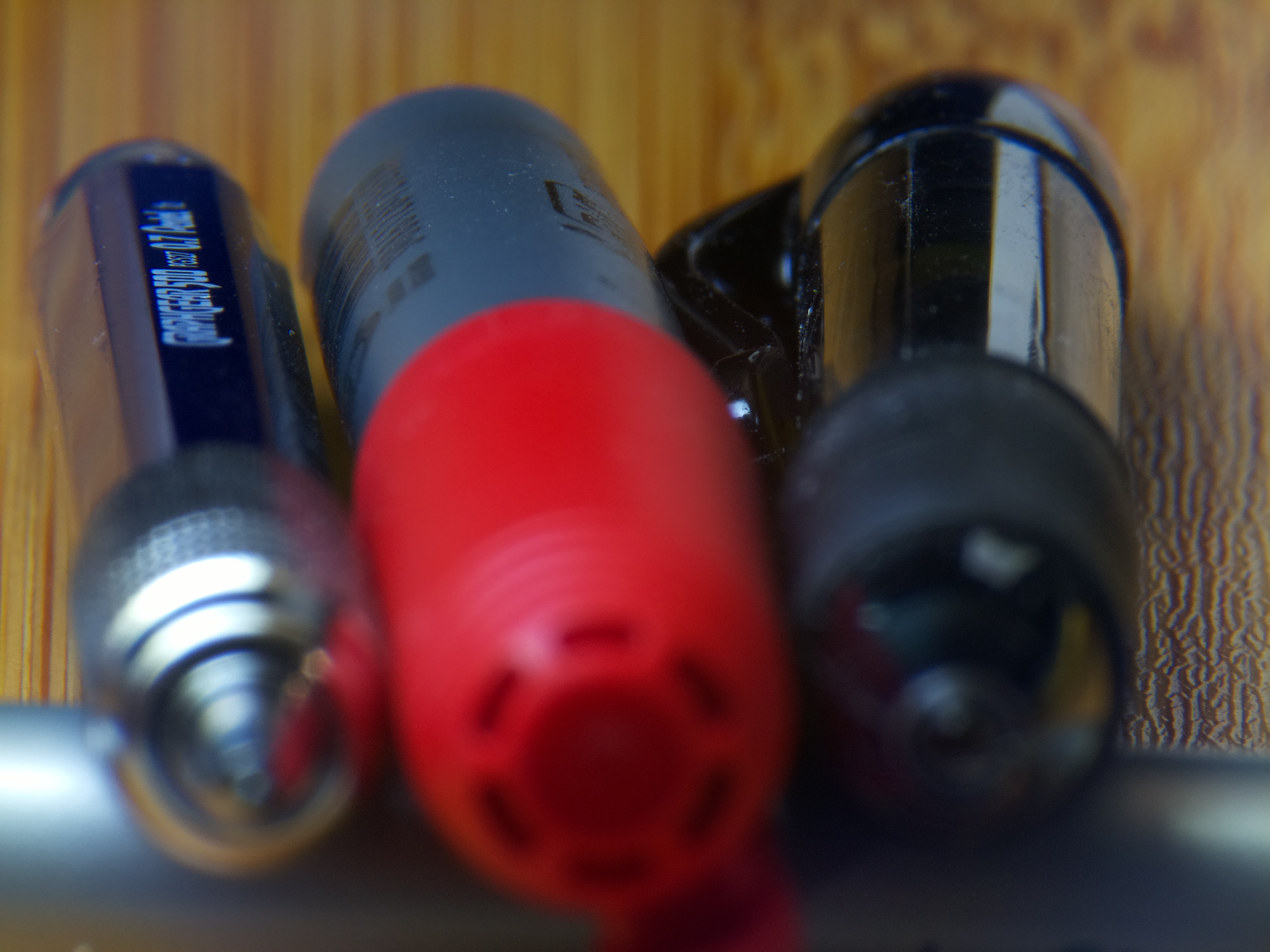
Some writing utencils
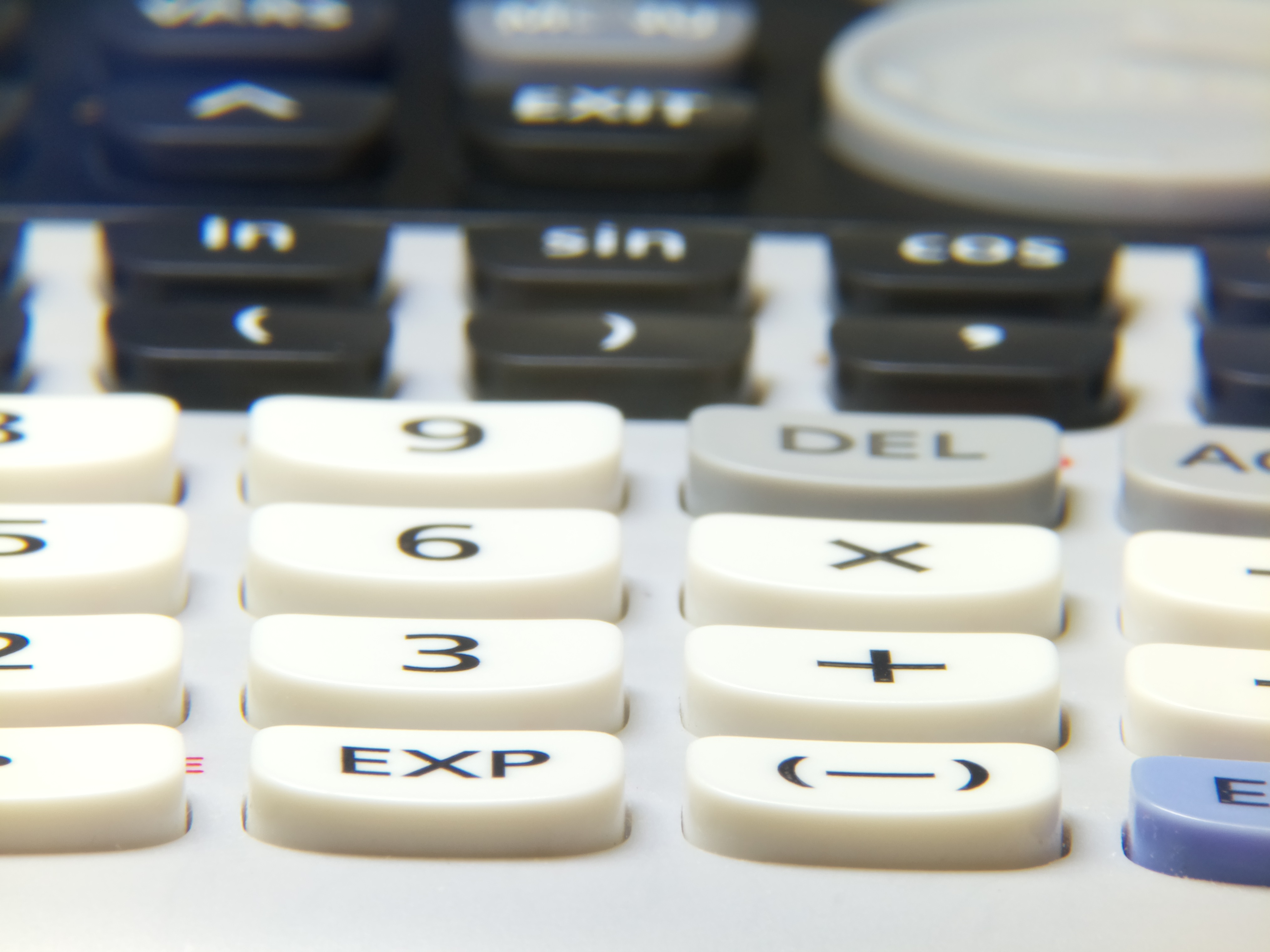
Keyboard of a graphics calculator
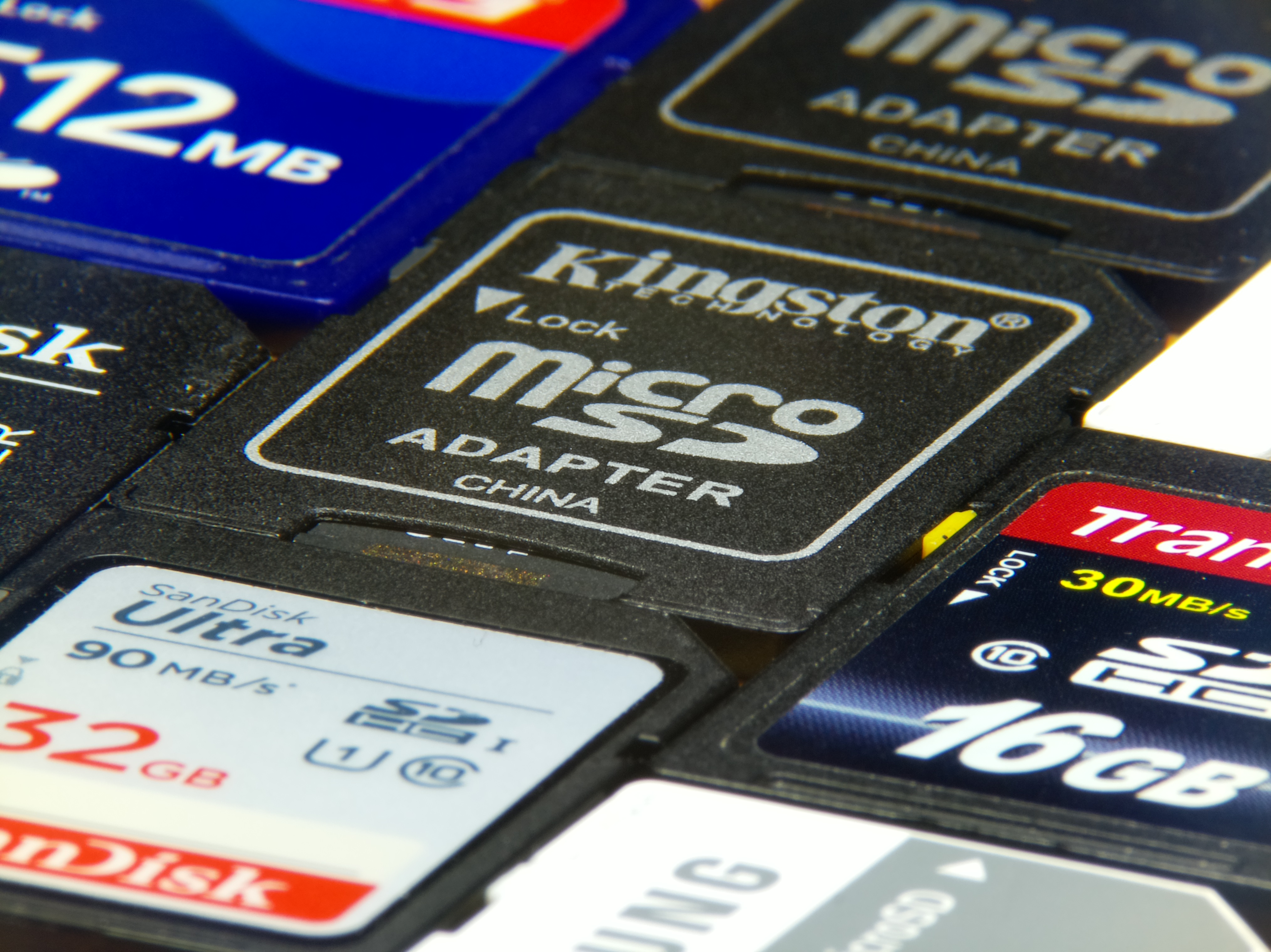
Some SD cards
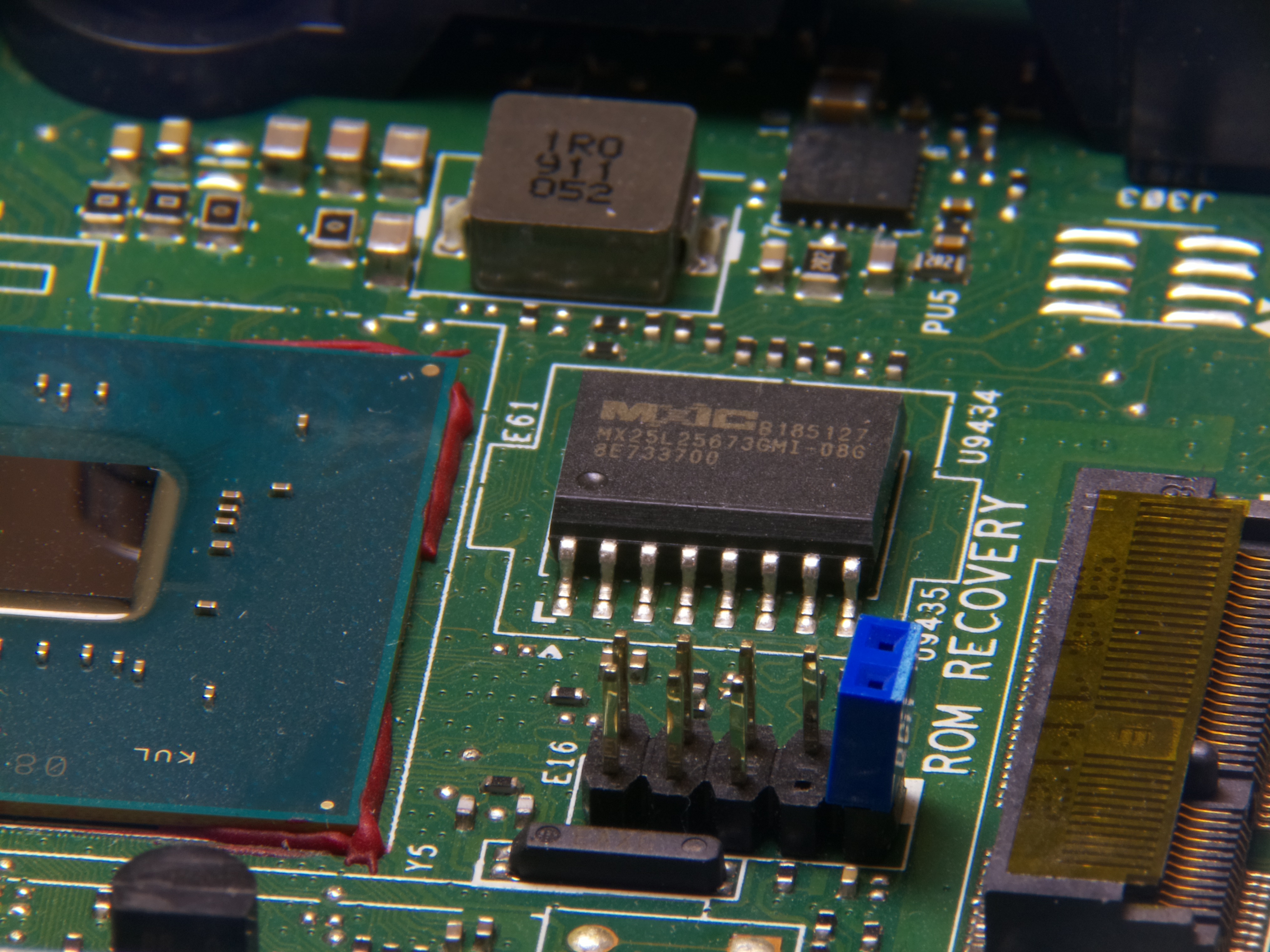
Motherboard of a mini PC
I’d say it worked out quite well! There was a weird bluish haze near the edges of the pictures, but I think that was a camera calibration issue that could be adjusted. Otherwise, I was able to get a decent depth of field, OK colors, and in general, pretty clear pictures.
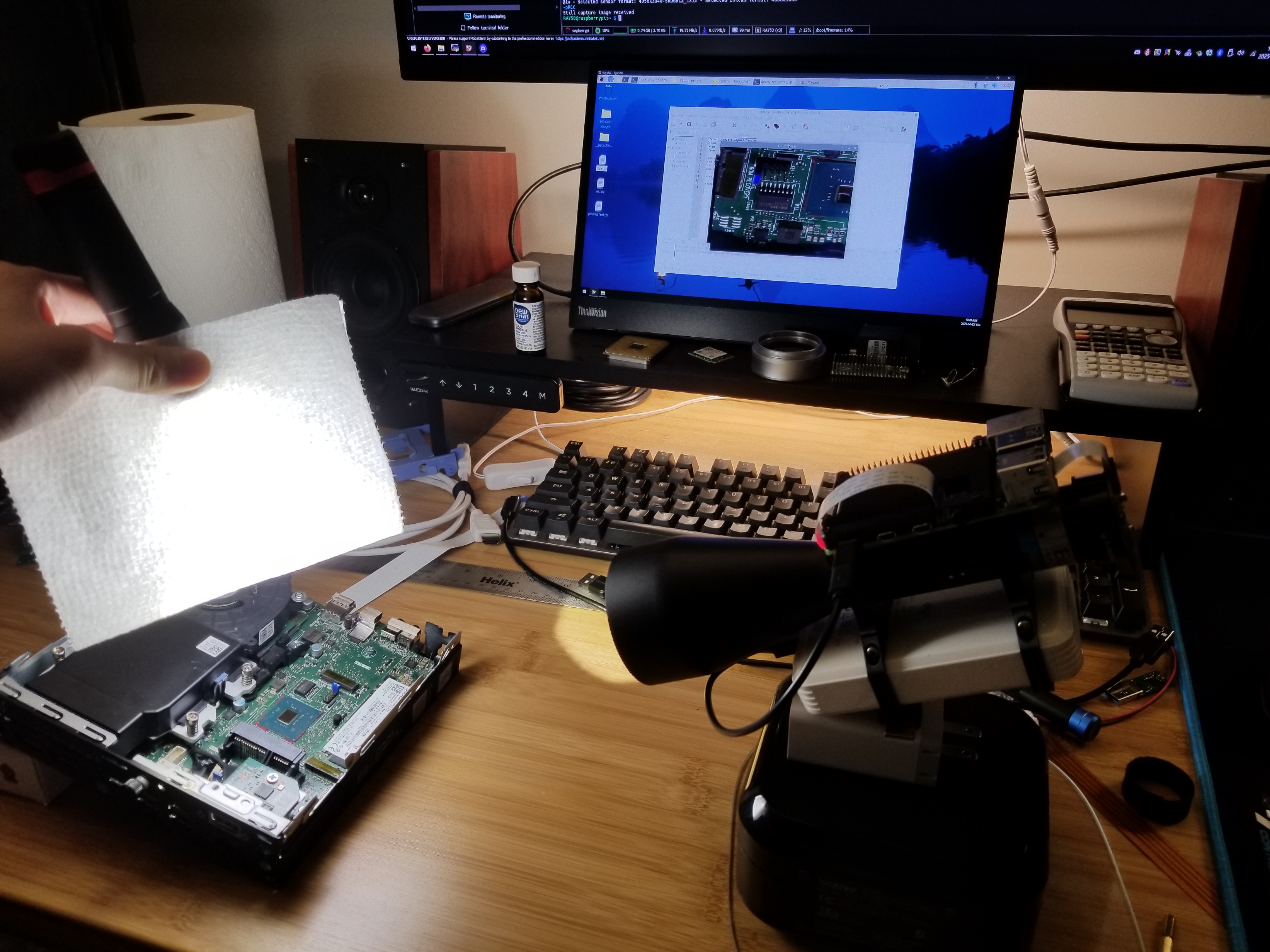
How I took the motherboard picture
Sony Mirrorless with C-Mount to E-Mount Adapter
Although the Canon DSLR experiment failed, I couldn’t put down the thought of mounting the lens onto a regular interchangeable-lens camera. After all, they have built-in displays, buttons, batteries for easy of use, not to mention tons of fancy image settings. One of my friends had a Sony α7 III mirrorless camera. Consulting the same Wiki page about flange focal distance , the value for Sony E-mount was 18 mm. This was very close to the 17.526 mm for C-mount, and a lens adapter with the correct design would work. He agreed to let me borrow the camera for testing purposes. I have to say, the pictures came out shockingly good.
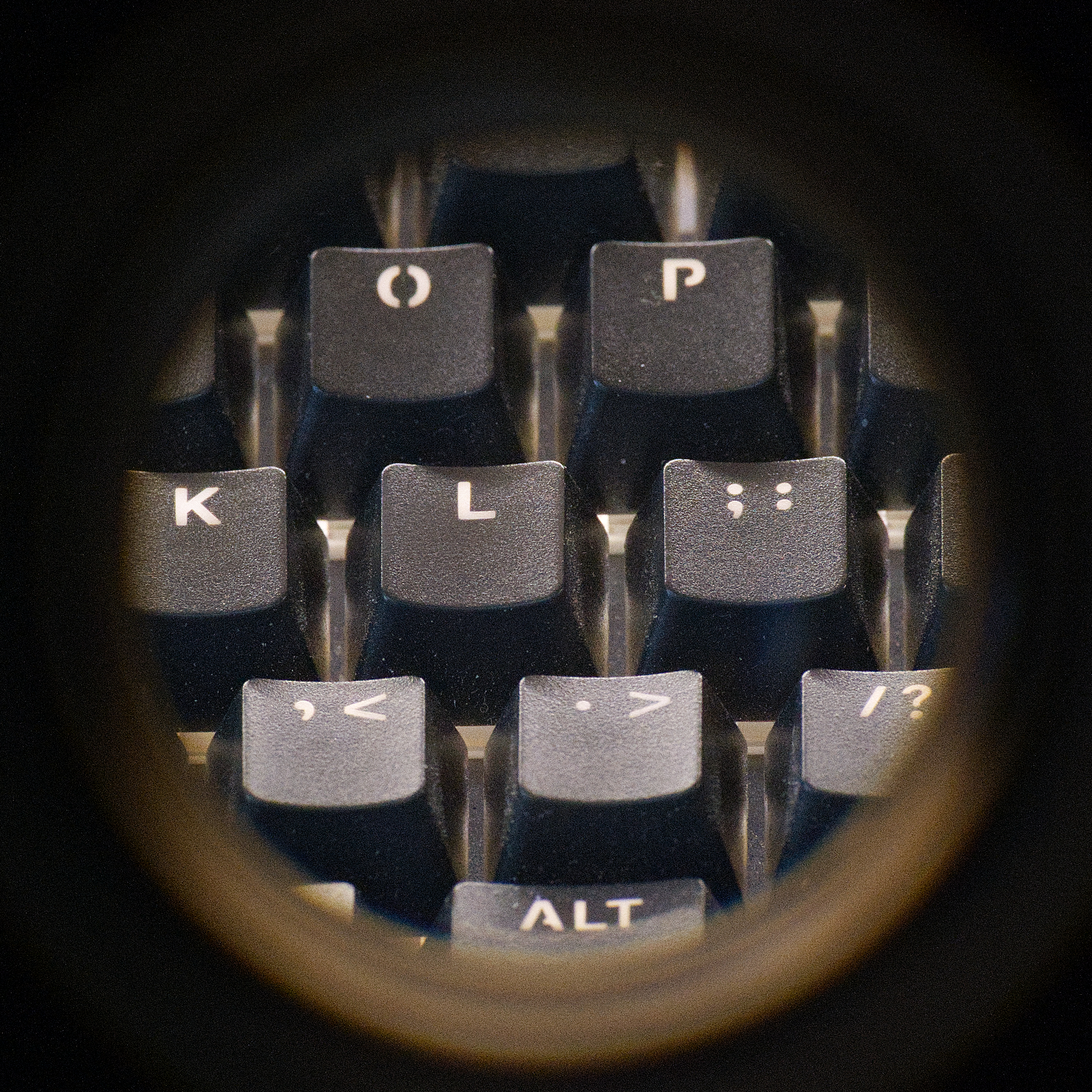
Some keys on a mechanical keyboard
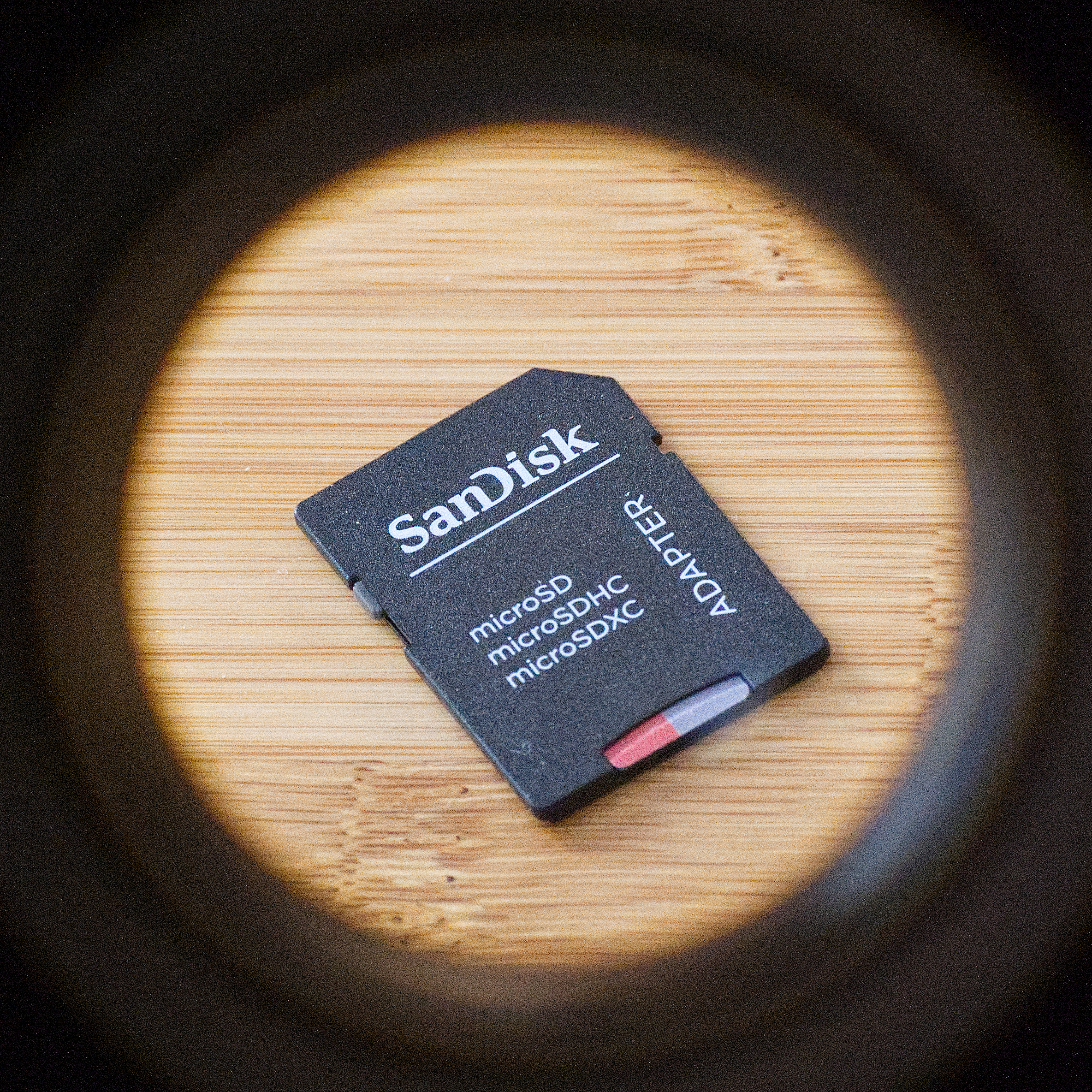
An SD card
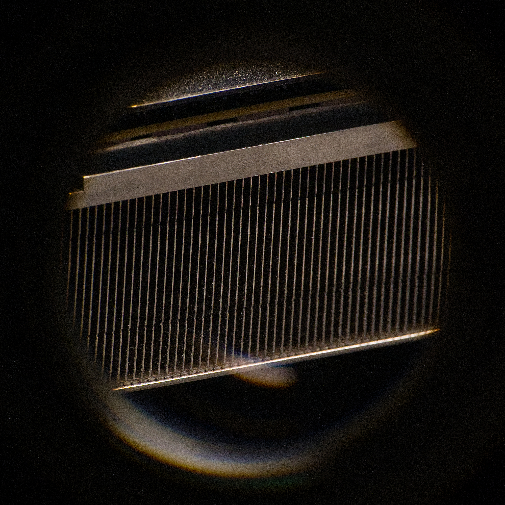
Heatsink of a graphics card
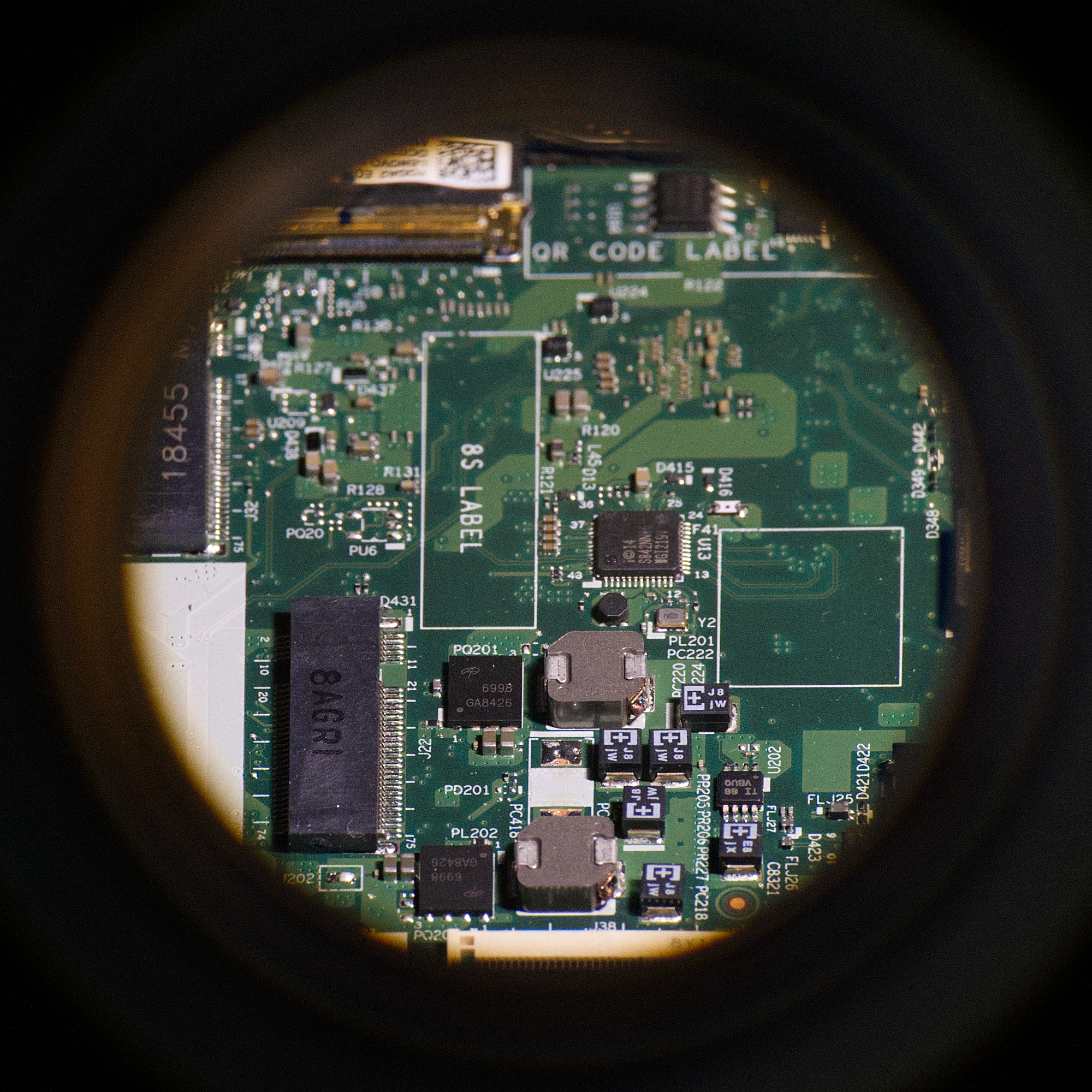
Motherboard of a laptop
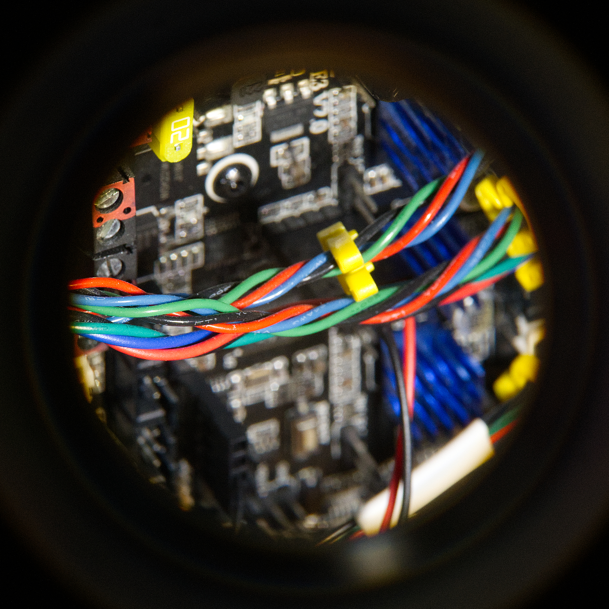
3D printer electronics
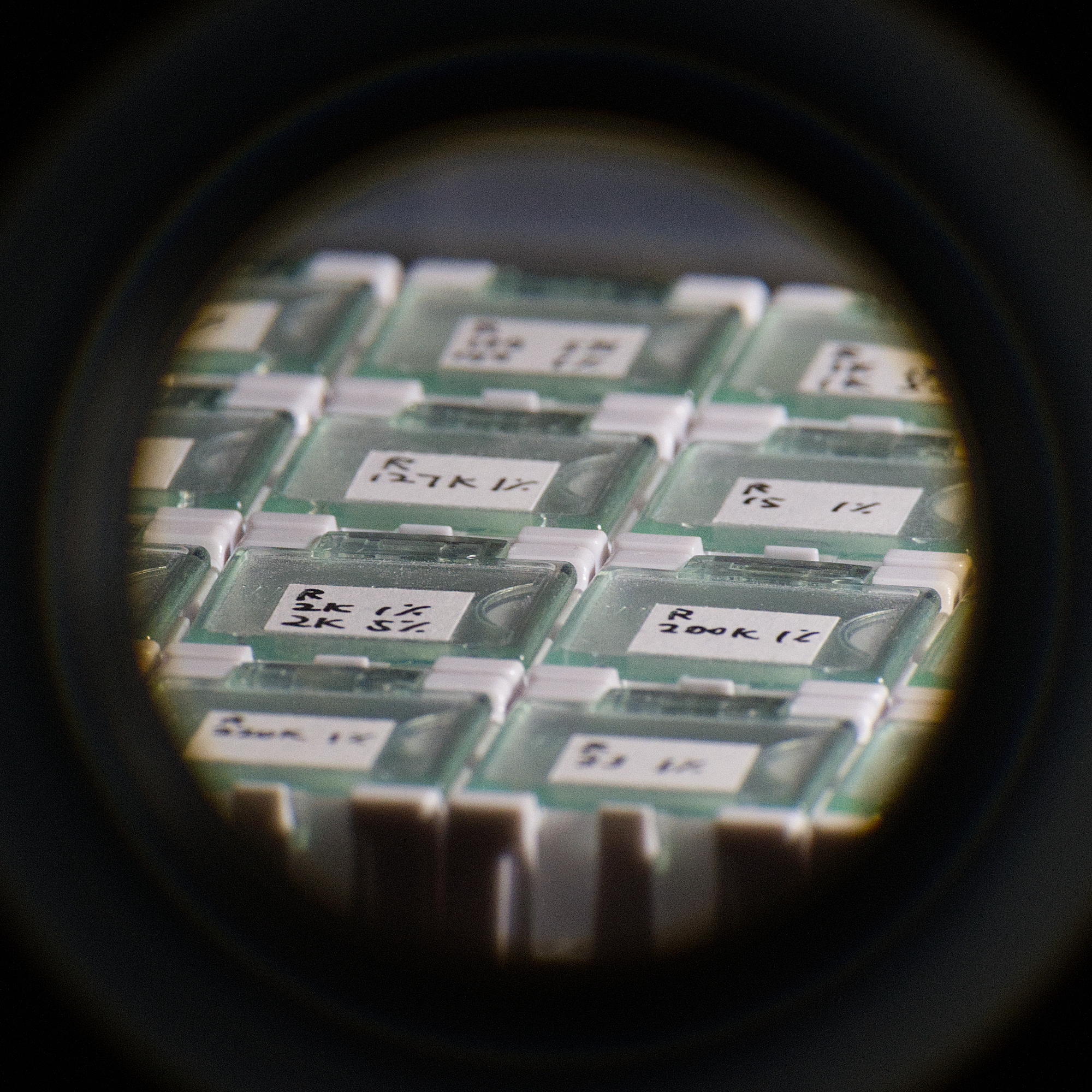
Some component organizers
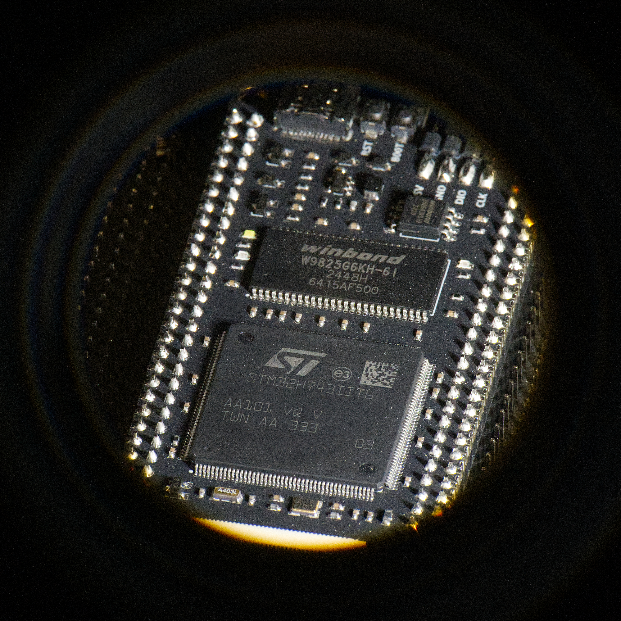
STM32 dev board
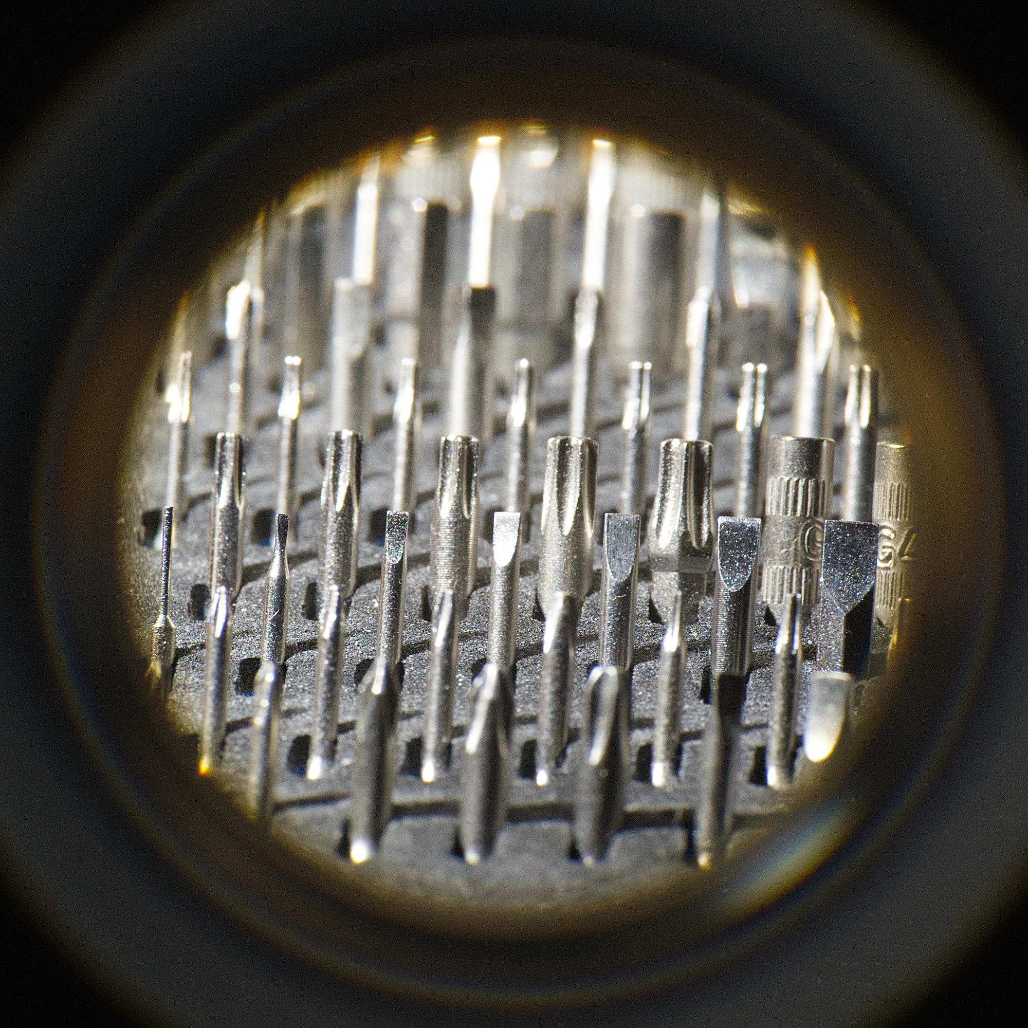
Screw driver bits
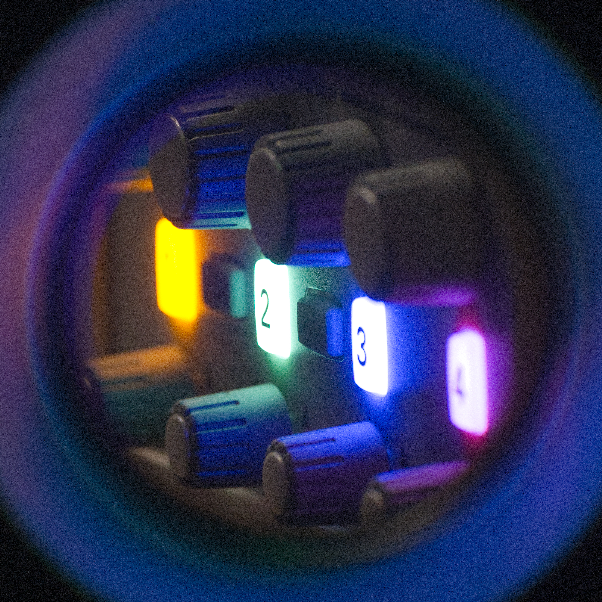
Front panel knobs and buttons of an oscilloscope
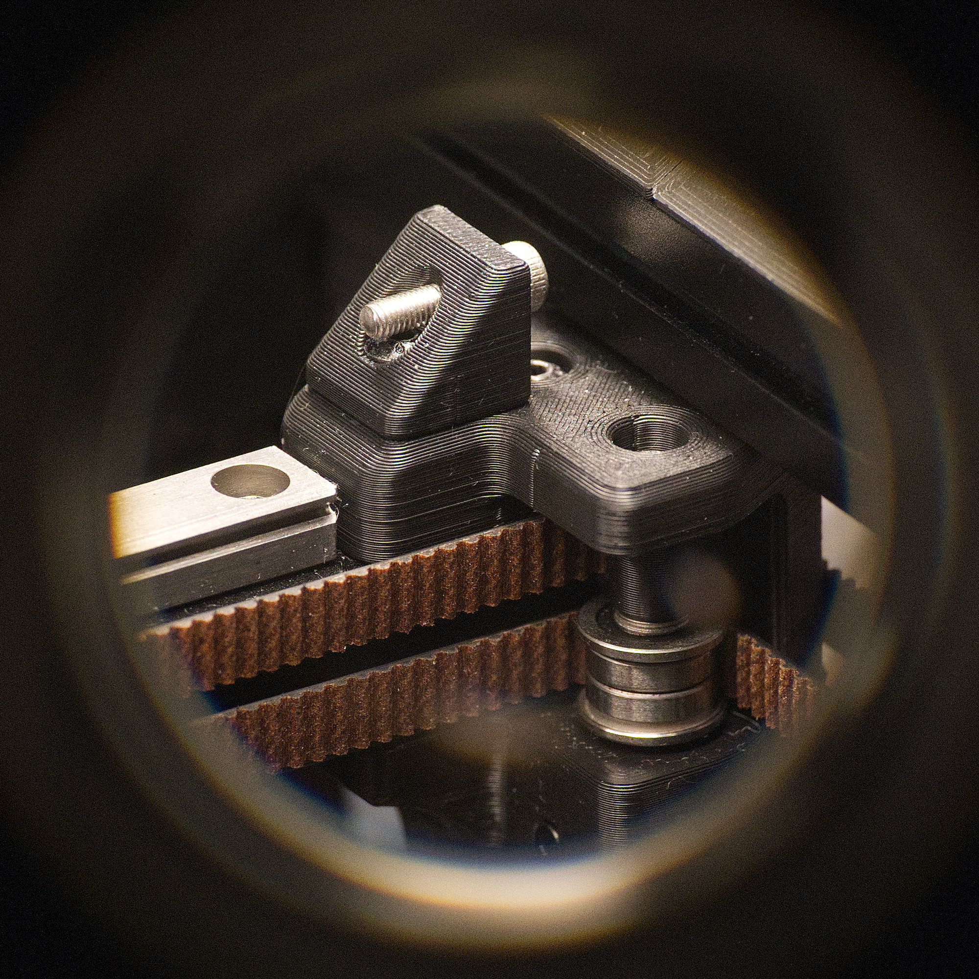
3D printer gantry mechanism
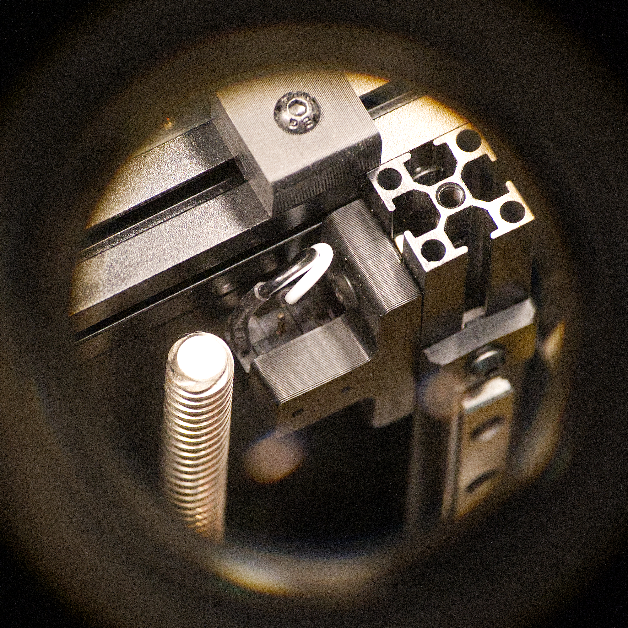
3D printer Z axis components
I did not expect the dust on the objects to be this visible (LOL). But the images themselves seemed to have no obvious defects. There was some film grain, but I think that was acceptable. I did post-process the raw files and crop the pictures to keep only the center 2000 by 2000 pixels, because it was just black elsewhere. Here’s a full picture without cropping, it’s kind of like looking through a tube. Overall, this combination was easy to use, created awesome pictures, but limited by resolution.
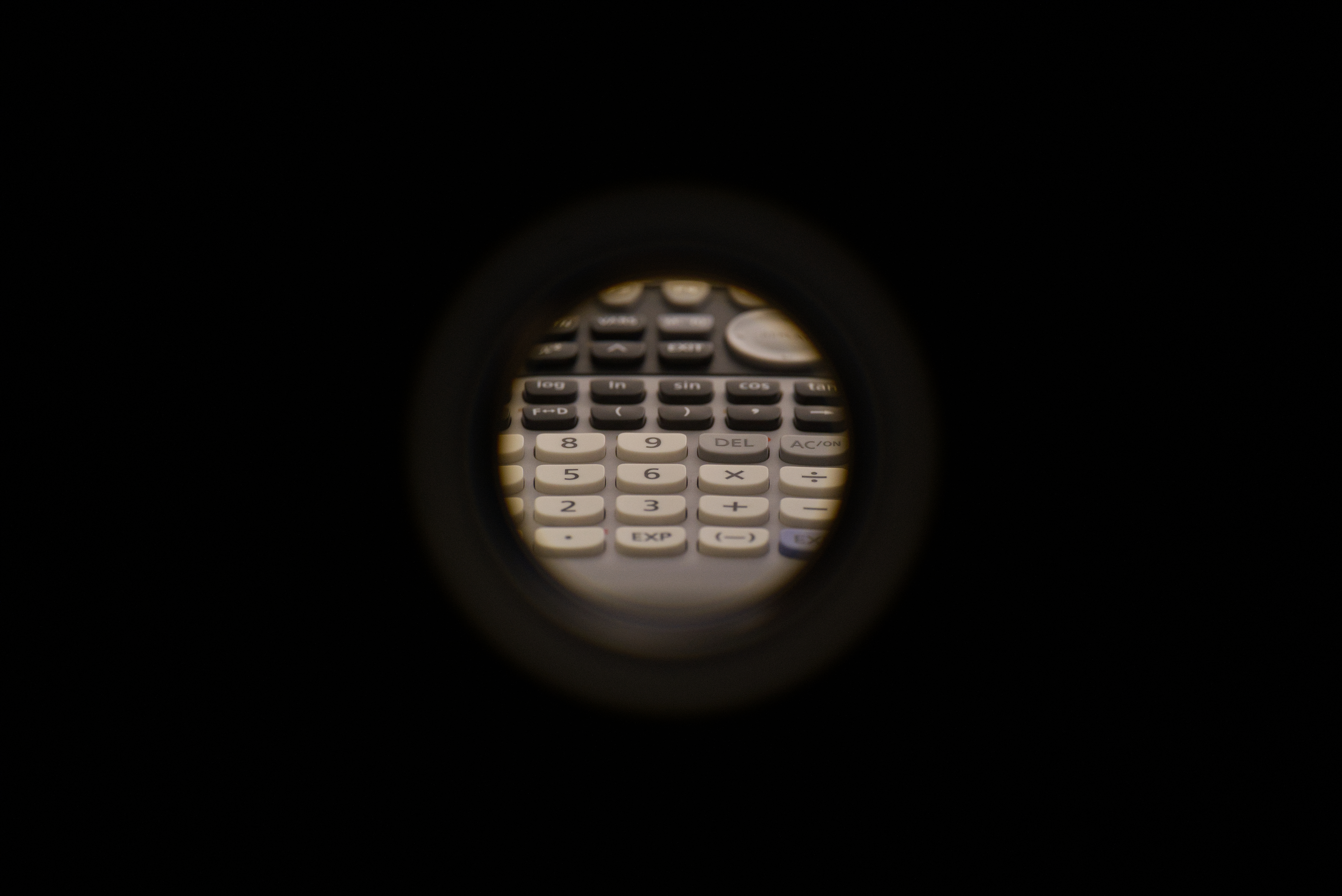
Uncropped image of the same graphics calculator featured in the Raspberry Pi section
FOV Comparison and Calculation
On both the Canon DSLR and the Sony mirrorless, the sensor was larger than the image projected by the lens. In such cases, it was possible to capture all the information coming from the lens. For the microscope camera and the Raspberry Pi camera, however, the sensor was smaller than the projected image. This eliminated the black part where no light hit the sensor, but came with the cost of throwing away edges of the image. I’ll use the calculator picture and the Image Sensor Format Wiki page as reference, and see how much was wasted exactly. Here’s the result.
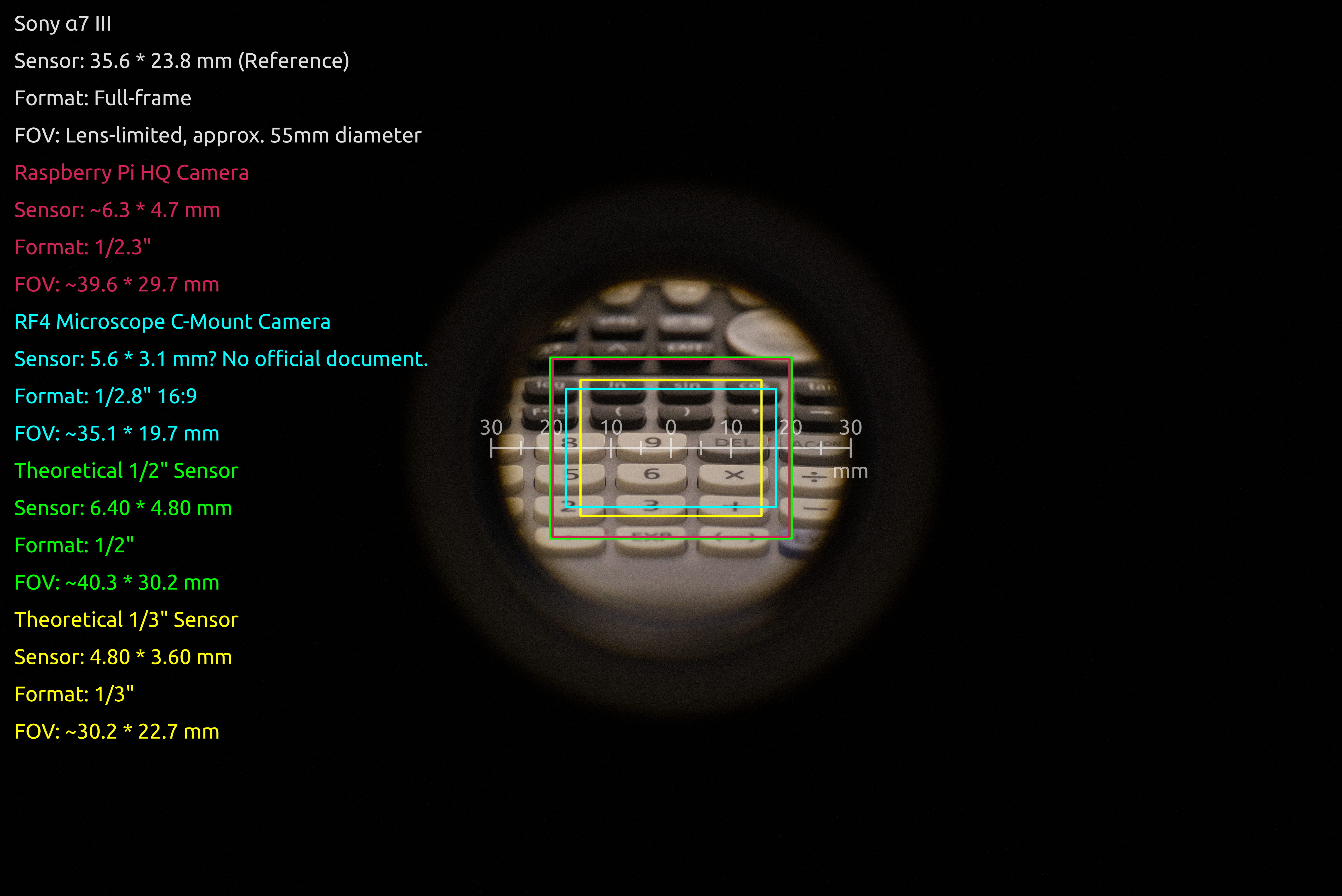
FOV Comparison
| Camera | Sensor | Format | FOV |
|---|---|---|---|
| Sony α7 III | 35.6 * 23.8 mm (Reference) | Full-frame | Lens-limited, approx. 55mm diameter |
| Raspberry Pi HQ Camera | ~6.3 * 4.7 mm | 1/2.3" | ~39.6 * 29.7 mm |
| RF4 Microscope C-Mount Camera | 5.6 * 3.1 mm? No official document. | 1/2.8" 16:9 | ~35.1 * 19.7 mm |
| Theoretical 1/2" Sensor | 6.40 * 4.80 mm | 1/2" | ~40.3 * 30.2 mm |
| Theoretical 1/3" Sensor | 4.80 * 3.60 mm | 1/3" | ~30.2 * 22.7 mm |
For each camera, I first looked up its sensor size, then scaled down their rectangles using the sensor size of the Sony α7 III as reference. The mm ruler was made by measuring the calculator with a pair of calipers. In hindsight, it would probably be a better idea to just take a picture of a ruler with each camera instead of doing manual measurement, losing precision in the process.
I didn’t find a reliable source for the sensor size of the RF4 microscope camera, so I just took a diagonal size of 6.4 mm according to this page , and calculated the H and V sizes with trigonometry. I used 16:9 aspect ratio instead of the typical 4:3 since it matched the output image resolution, and gave a better result when checking with the ruler test image captured with the camera.
The results made sense. The calculated FOV’s of the 2 theoretical sensors closely matched the numbers given by the lens’ spec sheet. The Raspberry Pi camera, despite having a smaller sensor than the 1/2" format on the spec sheet, did not lose much FOV when you compare their boxes. You can also see why the maximum sensor size recommended by Edmund (the lens manufacturer) was 1/2", if the FOV gets just a bit larger, the corners of the image will start experiencing distortion and vignetting. That would be unacceptable in industrial applications where the device was intended for.
Conclusions and Future Work
Although I didn’t find an all-rounder. I think the Raspberry Pi High Quality camera has the most potential going forward. It has decent image quality, and a good amount of customizability. It does, however, requires some development work to get a comfortable mechanical form-factor and a pain-free software workflow. The Sony α7 III had the best image quality, ease-of-use, and many advanced camera features, but the resolution was its Achilles’ heel. The other two options had obvious flaws and were not suitable for this project until I find a fix.
My next step would be to design a more robust enclosure to combine the Raspberry Pi, the HQ camera, and a battery shield into a proper “package” capable of handling daily use. The current mechanical design was still too fragile. The SSH and VNC workflow was surprisingly not too cumbersome in action. Since I will only use the camera next to my PC, having the image preview through a remote session, and being able to drag image files into my destination folder from MobaXterm, was actually quite convenient. With just an enclosure that can stand up to light abuse without accidently shorting everything out, and some conveniently placed tripod mounting points, I can see this being perfectly fine for what I need it for.
It was also possible that I simply missed an obvious existing camera due to a lack of knowledge in the photography space. Maybe there was a C-mount camera that was just as easy to use as an average DSLR or mirrorless? I don’t know. All of the ones I’ve seen were for microscopes, industrial, or some other obscure purposes. There are also C-mount astrophotography cameras. However, given that they have a very specialized feature set, I doubt they’ll be less trouble than the Raspberry Pi or even my microscope camera. I’ll update this post if I find a better solution, feel free to contact me if you have any ideas or suggestions.
Version History
2026-05-27: Initial release.